Back to Product Page
|
AIR
CURTAINS
|
|
FREE
FREIGHT
|
|
| FOR
ALL AIR CURTAINS SHIPPED TO LOCATIONS WITHIN THE 48 CONTIGUOUS
UNITED STATES |
|
|
|
|
 |
|
ENERGY |
|
Our
air curtains conserve energy and improve comfort by limiting
the escape of internal heat, reducing cold drafts and providing
a
welcoming down flow curtain of warm air at entrance ways in
industrial
plants and store buildings. The resulting mixture of warmed
air disperses
gently in all directions at floor level to give uniform temperature
over a
wide area from floor to ceiling with only a few degrees difference. |
|
|
|
 |
|
|
|
|
CONVENIENCE |
|
Our
air curtains allow personnel and cargo to pass freely from one
area to another while maintaining desired temperatures. |
|
|
|
An
added safety feature is the free flow of traffic with an unobstructed
view through the opening, eliminating doorway accidents. |
|
|
|
|
|
TYPICAL
USES |
|
Easily
mounted over entrance ways of warehouse doors up to 16 feet
high, the air curtains direct an invisible
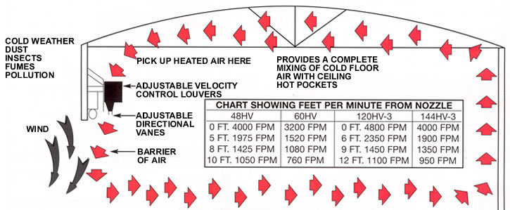
stream of stratified heated air downward. In addition to adding
to employee and customer comfort during
cold weather they provide important energy savings in three
ways: |
|
|
|
|
|
1.
In cold weather they reduce the load on heating systems. By
drawing warm air down to floor level where
it is needed, our air curtains utilize the 50% of wasted heated
air trapped under ceilings. Stratified air is
mixed and circulated with building heat and heat given off by
lights and machinery, etc. |
|
|
|
|
|
2.
The high velocity curtain of air deflects winds and reduces
excessive heat loss through open doorways. |
|
|
|
|
|
3.
During warm weather they can direct a stream of air downward
to help keep dust, dirt, insects and fumes
from entering through open doorways. If air conditioning exists
in the building during warm weather,
the air curtains can be used to prevent loss of conditioned
air as well. |
|
|
|
|
|
|
|
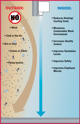
Our
air curtains create an invisible barrier of high
velocity air to stop cold or warm air infiltrating plant
facilities and work areas. |
 Stop entry of cold or warm air when doors are
open. |
|
Prevent the possibility of accidents with unobstructed
view of passageways. |
|
|
|
|
IMPORTANT:
MUST BE INSTALLED ON WARM
SIDE OF DOORWAY OPENING WHEN USED FOR
TEMPERATURE CONTROL |
Eliminate need for expensive plastic stripping, flapper
doors, or canvas curtains. |
|
Cold
weather can be further deterred at door opening if
space heater in plant is directed toward intake of the air
curtain. |
|
|
|
|
|
|
|
|
|
|
 |
|
|
|
|
|
|
|
| SPECIFICATIONS
AND FEATURES |
|
|
|
|
|
| FOR
ARCHITECTS AND ENGINEERS |
|
EASY
INSTALLATION |
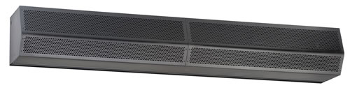
Our
air curtains shall have a self-contained one piece
housing, fire retardant and corrosion proof, in-
corporated with a double extended shaft motor, direct
drive double width and double inlet squirrel cage blower
wheels and fan housings. |
|
Our
air curtains are bolted to wall with four fasteners
and connected to electric power source. |
|
AIR
VELOCITY CONTROL FOR VARIABLE
AIR SPEED |
|
Adjustable
louver damper controls are provided in
order to adjust rate of air flow. |
Shall
have wedge shaped discharge nozzle containing
adjustable air deflectors with 40% sweep front to back. |
|
|
When
used over a doorway to retain warm or cold
temperature, proper velocity adjustment is imperative
for maximum efficiency. Velocity Control can reduce
air velocity up to 60% with louvers in totally closed
position. |
Housing
shall be sufficient strength for fastening to wall
on both ends without any intermediate support. |
|
| HEAVY
DUTY ELECTRIC MOTOR |
|
Continuous
duty type motor with double sealed lifetime
pre-lubricated stainless steel ball bearings, resilient
mounted and protected by an automatic thermal overload
switch. Underwriters Laboratories Listed and Canadian
Standards Association Certified. Explosion proof motors
available. |
|
|
AIR
DIRECTIONAL CONTROL |
|
Adjustable
vanes at outlet nozzle for directing air
to compensate for possible draft conditions through
doorways. |
|
|
|
|
| FIRE
RETARDANT AND CORROSION PROOF |
|
|
How
Air Curtain Works
|
|
Steel
models are of 18 gauge paintlock metal and double
protected with gray, baked, rust preventative electrostatic
polyurethane powder coating. |
|
|
 |
|
| NOISE
LEVEL |
|
|
|
Our
air curtains operate under a low noise level in the
interest and comfort of personnel working in the immediate
vicinity. |
|
|
|
|
|
|
|
|
|
SELECTION
TABLE
|
|
Model
No.
|
Width
of Door
|
Door
Height
|
FLA
(Ampacity) Single Phase
|
Sound
dBA
|
Weight
(lbs)
|
|
115V
|
208V/230V
|
|
STD236
|
36"
|
8'
- 10'
|
5.1
|
2.5
/ 2.5
|
66
|
50
|
|
STD242
|
42"
|
8'
- 10'
|
5.1
|
2.5
/ 2.5
|
66
|
55
|
|
STD248
|
48"
|
8'
- 10'
|
5.1
|
2.5
/ 2.5
|
66
|
60
|
|
STD264-2
|
64"
|
8'
- 10'
|
10.2
|
5.0
/ 5.0
|
68
|
95
|
|
STD272-2
|
72"
|
8'
- 10'
|
10.2
|
5.0
/ 5.0
|
68
|
100
|
|
STD278-2
|
78"
|
8'
- 10'
|
10.2
|
5.0
/ 5.0
|
68
|
110
|
|
STD284-2
|
84"
|
8'
- 10'
|
10.2
|
5.0
/ 5.0
|
68
|
115
|
|
STD296-2
|
96"
|
8'
- 10'
|
10.2
|
5.0
/ 5.0
|
68
|
125
|
|
STD296-3
|
96"
|
8'
- 10'
|
15.3
|
7.5
/ 7.5
|
71
|
170
|
|
STD2108-2
|
108"
|
8'
- 10'
|
10.2
|
5.0
/ 5.0
|
71
|
130
|
|
STD2108-3
|
108"
|
8'
- 10'
|
15.3
|
7.5
/ 7.5
|
71
|
175
|
|
STD2120-3
|
120"
|
8'
- 10'
|
15.3
|
7.5
/ 7.5
|
71
|
185
|
|
STD2144-3
|
144"
|
8'
- 10'
|
15.3
|
7.5
/ 7.5
|
71
|
205
|
|
STD2144-4
|
144"
|
8'
- 10'
|
20.4
|
10.0
/ 10.0
|
73
|
215
|
|
HV242
|
42"
|
10'
- 12'
|
3.3
/ 3.2
|
1.6
|
70
|
90
|
|
HV248
|
48"
|
10'
- 12'
|
3.3
/ 3.2
|
1.6
|
70
|
95
|
|
HV260
|
60"
|
10'
- 12'
|
3.3
/ 3.2
|
1.6
|
70
|
105
|
|
HV272-2
|
72"
|
10'
- 12'
|
6.6
/ 6.4
|
3.2
|
73
|
165
|
|
HV284-2
|
84"
|
10'
- 12'
|
6.6
/ 6.4
|
3.2
|
73
|
180
|
|
HV296-2
|
96"
|
10'
- 12'
|
6.6
/ 6.4
|
3.2
|
73
|
190
|
|
HV296-3
|
96"
|
10'
- 12'
|
9.9
/ 9.6
|
4.8
|
75
|
240
|
|
HV2108-2
|
108"
|
10'
- 12'
|
6.6
/ 6.4
|
3.2
|
73
|
200
|
|
HV2108-3
|
108"
|
10'
- 12'
|
9.9
/ 9.6
|
4.8
|
75
|
255
|
|
HV2120-2
|
120"
|
10'
- 12'
|
6.6
/ 6.4
|
3.2
|
73
|
215
|
|
HV2120-3
|
120"
|
10'
- 12'
|
9.9
/ 9.6
|
4.8
|
75
|
270
|
|
HV2144-3
|
144"
|
10'
- 12'
|
9.9
/ 9.6
|
4.8
|
75
|
295
|
|
HV2144-4
|
144"
|
10'
- 12'
|
13.2
/ 12.8
|
6.4
|
75
|
375
|
|
EP248
|
48"
|
14'
- 16'
|
8.3
/ 7.6
|
3.8
|
76
|
100
|
|
EP260
|
60"
|
14'
- 16'
|
8.3
/ 7.6
|
3.8
|
76
|
115
|
|
EP272-2
|
72"
|
14'
- 16'
|
16.6
/ 15.2
|
7.6
|
79
|
170
|
|
EP284-2
|
84"
|
14'
- 16'
|
16.6
/ 15.2
|
7.6
|
79
|
190
|
|
EP296-2
|
96"
|
14'
- 16'
|
16.6
/ 15.2
|
7.6
|
79
|
200
|
|
EP2108-2
|
108"
|
14'
- 16'
|
16.6
/ 15.2
|
7.6
|
79
|
210
|
|
EP2108-3
|
108"
|
14'
- 16'
|
24.9
/ 22.8
|
11.4
|
81
|
265
|
|
EP2120-2
|
120"
|
14'
- 16'
|
16.6
/ 15.2
|
7.6
|
79
|
225
|
|
EP2120-3
|
120"
|
14'
- 16'
|
24.9
/ 22.8
|
11.4
|
81
|
280
|
|
EP2144-3
|
144"
|
14'
- 16'
|
24.9
/ 22.8
|
11.4
|
81
|
305
|
|
|
 |
 |
|
|
|
Understanding
Series Order Codes
|
 |
|
|
 |
|
Order
Online, by Phone, or by E-Mail |
|
|
|
~
Add items to your online shopping cart ~
Click the Model No. of the item
you wish to purchase.
|
|
|
|
|
|
|
|
|
| Standard
Features: |
|
Made
in the USA |
|
Standard Color:
|
|
|
|
|
 |
|
| 1/2
HP Direct Drive |
|
Easy
install |
Protection |
|
| Three-speed
controller |
|
Motor
Fan Assembly |
Environmetal:
10' |
|
| Sleek
metal design |
|
5-year
warranty |
Flying-insects:
8' |
|
|
|
|
|
|
|
|
|
|
|
|
|
PRICING
AND SPECIFICATIONS FOR STANDARD - (UNHEATED
MODELS)
|
|
Models
|
Voltage
|
Air
Volume (max.)
|
Length
|
Height
|
Depth
|
Full-Load
Draw
|
*Control
Device Requirement
|
Wgt.
(lbs)
|
Avg.
Velocity
|
Uniformity
(%)
|
Power
Rating
|
#
of motors
|
PRICE
|
|
|
115/1/60
|
1379cfm
|
36"
|
10
5/8"
|
12
3/4"
|
5.1amps
|
C
|
60
|
2206fpm
|
84
|
500watts
|
1
|
$1,156
|
|
|
208-230/1/60
|
2.7amps
|
C
|
$1,156
|
|
|
208-230/3/60
|
1.8-1.6amps
|
R
|
$1,280
|
|
|
460/3/60
|
0.8amps
|
R
|
$1,280
|
|
|
115/1/60
|
1418cfm
|
42"
|
10
5/8"
|
12
3/4"
|
5.1amps
|
C
|
65
|
1945fpm
|
87
|
510watts
|
1
|
$1,190
|
|
|
208-230/1/60
|
2.7amps
|
C
|
$1,190
|
|
|
208-230/3/60
|
1.8-1.6amps
|
R
|
$1,315
|
|
|
460/3/60
|
0.8amps
|
R
|
$1,315
|
|
|
115/1/60
|
1442cfm
|
48"
|
10
5/8"
|
12
3/4"
|
5.1amps
|
C
|
70
|
1730fpm
|
85
|
550watts
|
1
|
$1,227
|
|
|
208-230/1/60
|
2.7amps
|
C
|
$1,227
|
|
|
208-230/3/60
|
1.8-1.6amps
|
R
|
$1,351
|
|
|
460/3/60
|
0.8amps
|
R
|
$1,351
|
|
|
115/1/60
|
2700cfm
|
60"
|
10
5/8"
|
12
3/4"
|
10.2amps
|
C
|
90
|
2592fpm
|
93
|
940watts
|
2
|
$1,837
|
|
|
208-230/1/60
|
5amps
|
C
|
$1,837
|
|
|
208-230/3/60
|
3.6-3.2amps
|
R
|
$2,084
|
|
|
460/3/60
|
1.6amps
|
R
|
$2,084
|
|
|
115/1/60
|
2758cfm
|
72"
|
10
5/8"
|
12
3/4"
|
10.2amps
|
C
|
120
|
2206fpm
|
84
|
1000watts
|
2
|
$2,000
|
|
|
208-230/1/60
|
5amps
|
C
|
$2,000
|
|
|
208-230/3/60
|
3.6-3.2amps
|
R
|
$2,247
|
|
|
460/3/60
|
1.6amps
|
R
|
$2,247
|
|
|
115/1/60
|
2836cfm
|
84"
|
10
5/8"
|
12
3/4"
|
10.2amps
|
C
|
125
|
1945fpm
|
87
|
1020watts
|
2
|
$2,213
|
|
|
208-230/1/60
|
|
|
|
|
5amps
|
C
|
$2,213
|
|
|
208-230/3/60
|
|
|
|
|
3.6-3.2amps
|
R
|
$2,461
|
|
|
460/3/60
|
|
|
|
|
1.6amps
|
R
|
$2,461
|
|
|
|
|
|
|
|
|
Models
|
Voltage
|
Air
Volume (max.)
|
Length
|
Height
|
Depth
|
Full-Load
Draw
|
*Control
Device Requirement
|
Wgt.
(lbs)
|
Avg.
Velocity
|
Uniformity
(%)
|
Power
Rating
|
#
of motors
|
PRICE
|
| STD2 96-2UA-OB |
115/1/60
|
2884cfm
|
96"
|
10
5/8"
|
12
3/4"
|
10.2amps
|
C
|
135
|
1730fpm
|
85
|
1100watts
|
2
|
$2,383
|
| STD2 96-2UD-OB |
208-230/1/60
|
5amps
|
C
|
$2,383
|
| STD2 96-2UG-OB |
208-230/3/60
|
3.6-3.2amps
|
R
|
$2,631
|
|
|
208-230/3/60
|
1.6amps
|
R
|
$2,631
|
| STD2 108-3UA-OB |
115/1/60
|
4137cfm
|
108"
|
10
5/8"
|
12
3/4"
|
15.3amps
|
R
|
175
|
2206fpm
|
84
|
1500watts
|
3
|
$3,232
|
| STD2 108-3UD-OB |
208-230/1/60
|
7.5amps
|
R
|
$3,232
|
| STD2 108-3UG-OB |
208-230/3/60
|
5.4-4.8amps
|
R
|
$3,603
|
| STD2 108-3UH-OB |
460/3/60
|
2.4amps
|
R
|
$3,603
|
| STD2 120-3UA-OB |
115/1/60
|
4341cfm
|
120"
|
10
5/8"
|
12
3/4"
|
15.3amps
|
R
|
185
|
2084fpm
|
92
|
1570watts
|
3
|
$3,339
|
| STD2 120-3UD-OB |
208-230/1/60
|
7.5amps
|
R
|
$3,339
|
| STD2 120-3UG-OB |
208-230/3/60
|
5.4-4.8amps
|
R
|
$3,710
|
| STD2 120-3UH-OB |
460/3/60
|
2.4amps
|
R
|
$3,710
|
| STD2 144-3UA-OB |
115/1/60
|
4326cfm
|
144"
|
10
5/8"
|
12
3/4"
|
15.3amps
|
R
|
200
|
1730fpm
|
85
|
1650watts
|
3
|
$3,625
|
| STD2 144-3UD-OB |
208-230/1/60
|
7.5amps
|
R
|
$3,625
|
| STD2 144-3UG-OB |
208-230/3/60
|
5.4-4.8amps
|
R
|
$3,996
|
| STD2 144-3UH-OB |
460/3/60
|
2.4amps
|
R
|
$3,996
|
|
*Control
device requirement
C - Separate Relay or Relay With Time Delay conditionally
required
I - Internally mounted control panel included
R - Separate externally mounted Control Panel required
|
|
 |
|
OB
|
|
TS
|
|
PW
|
|
|
|
|
|
|
|
|
| Optional
Colors Available - Std. Production Color is Obsidian
Black (matte) See add-on prices below. |
|
|
|
|
|
|
|
|
Prices for Colors That are not Standard for the Series
(add these prices to price of
standard air curtain)
|
|
Length of Unit |
25" |
36" |
42" |
48" |
60" |
64" |
72" |
84" |
96" |
108" |
120" |
144" |
| TS |
|
|
|
|
|
|
|
|
|
|
|
|
| PW |
|
|
|
|
|
|
|
|
|
|
|
|
|
|
|
 |
|
Order
Online, by Phone, or by E-Mail |
|
|
|
~
Add items to your online shopping cart ~
Click the Part No. of the item
you wish to purchase.
|
|
|
|
|
STANDARD
SERIES ACCESSORIES - UNHEATED
MODELS
|
|
|
DOOR
SWITCHES
|
| Automatic
on/off control of air curtain as door is opened and closed |
|
Line
Voltage
|
|
Part
No.
|
Package
|
Price
|
|
|
Door
Limit Switch - Combination roller and plunger - 20 amps, 250v, or 1 hp
max.
|
$141.50
|
|
24
VOLT CONTROL
|
|
Part
No.
|
Package
|
Price
|
|
|
Commercial
Magnetic Reed Switch Only
- Plastic - Surface Mounted -
Note: Used with control packages for double doors
|
$66.10
|
|
CONTROL
PACKAGES
|
| Combination
packages of door switches, controllers, time delays, and
thermostats |
| 24
VOLT CONTROL |
|
Part
No.
|
Package
|
Price
|
|
|
Commercial
Magnetic Reed Switch with Controller and Adjustable
Time Delay - 115v.
6 sec. - 20 min., plastic,
surface-mounted.
|
$385.30
|
|
|
Commercial
Magnetic Reed Switch with Adjustable Time Delay
• 208-230v 1Ø
6 sec.- 20 min. · Plastic · Surface-mounted
|
$385.30
|
|
|
Commercial
Magnetic Reed Switch with Controller • 115v
-
Plastic, Surface-mounted
|
$286.20
|
|
|
Commercial
Magnetic Reed Switch with Controller • 208-230v
1Ø
Plastic • Surface-mounted
|
$286.20
|
|
|
Door
Limit Switch with Controller and Adjustable Time Delay
• 115v
6 sec.- 20 min. •
Surface-mounted
|
$440.30
|
|
|
Door
Limit switch with Controller and Adjustable Time Delay
• 208-230v 1Ø
6 sec.- 20 min. • Surface-mounted
|
$440.30
|
|
|
|
|
|
Order
Online, by Phone, or by E-Mail |
|
|
|
~
Add items to your online shopping cart ~
Click the Part No. of the item
you wish to purchase.
|
|
|
|
|
|
|
|
|
MOTOR CONTROL PANELS |
Remote-mounted
control panels for all 3Ø units and 1Ø units
when greater than 1 hp (NEMA 1) · Units come
standard with HOA (hand/off/auto) switch · Panel
shipped loose · Standard color Battleship Gray
· NOTE: Electric
heated units include internal control panel and remote-mounted
24v thermostat with heat/off/fan only switch
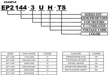
[vc] Voltage codes: A = 115/1/60 D = 208-230/1/60 G
= 208-230/3/60 H = 460/3/60 U = 220/1/50 |
|
Part No. |
Description |
Price |
|
|
One
Motor Control Panel 1/2 HP - specify required voltage |
$1,111.90
|
|
|
Two
Motor Control Panel 1/2 HP -
specify required voltage |
$1,591.50
|
|
|
Three
Motor Control Panel 1/2 HP
- specify required voltage |
$1,997.30
|
|
|
Four
Motor Control Panel 1/2 HP - specify required voltage |
$2,365.30
|
|
|
Five
Motor Control Panel 1/2 HP - specify required voltage |
$3,016.30
|
|
|
Six
Motor Control Panel 1/2 HP - specify required voltage |
$3,602.90
|
|
| *Add
code for required voltage from chart above. |
|
|
MOUNTING BRACKETS
|
|
Part No. |
Mounting Bracket |
Price |
Recommended
for specific applications · Standard color Titanium
Silver
· NOTE: Units come standard with predrilled holes
on back end for flush mounting |
|
|
5"
Flat Side Extension Plates - to
clear track on either end - Set of 2 |
$165.10
|
|
|
7"
Flat Side Extension Plates - to
clear track on either end - Set of 2 |
$165.10
|
|
|
9"
Flat Side Extension Plates - to
clear track on either end - Set of 2 |
$165.10
|
|
|
2
1/2"-Clearance Adjustable-Angle Mounting Bracket
To clear wall obstructions - Set of 2 |
$165.10
|
|
|
4"-Clearance
Adjustable-Angle Mounting Bracket
To clear wall obstructions - Set of 2 |
$330.30
|
|
|
7"-Clearance
Adjustable-Angle Mounting Bracket
To clear wall obstructions - Set of 2 |
$330.30
|
|
|
10"-Clearance
Adjustable-Angle Mounting Bracket
To clear wall obstructions - Set of 2 |
$330.30
|
|
|
10"-Clearance
Drum-Roll-Style Extended Wall Mounting Bracket
For use over drum-style roll-up
doors - Set of 2 |
$396.30
|
|
|
16"-Clearance
Drum-Roll-Style Extended Wall Mounting Bracket
For use over drum-style roll-up
doors - Set of 2 |
$396.30
|
|
|
19"-Clearance
Drum-Roll-Style Extended Wall Mounting Bracket
For use over drum-style roll-up
doors - Set of 2 |
$418.30
|
|
|
23"-Clearance
Drum-Roll-Style Extended Wall Mounting Bracket
For use over drum-style roll-up
doors - Set of 2 |
$506.40
|
|
|
FILTERS |
|
Part No. |
Filters |
Price |
|
FLTR |
Aluminum Mesh Filter (1/4") - internal mount - (Size):
Specify size in inches
(Set of 2) |
$3.10/per in. |
|
|
|
|
|
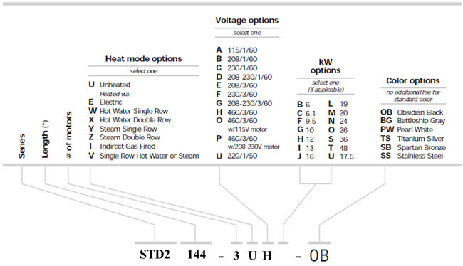
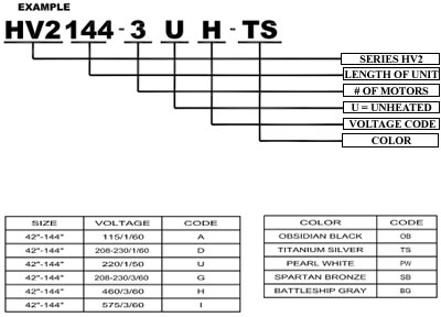
MODEL
NUMBER CONFIGURATION |
|
|
|
|
 |
|
 |
|
|
|
|
|
Standard
features
1 hp direct-drive motor
Sleek metal design
Easy install
Motor fan assembly
5-year warranty
Made in USA |
Protection
Environmental: 12’
Flying-insects: 10’ |
|
|
|
|
| Standard
color: |
|
 |
|
|
|
|
|
|
|
|
|
|
|
|
|
Order
Online, by Phone, or by E-Mail |
|
|
|
~
Add items to your online shopping cart ~
Click the Model No. of the item
you wish to purchase.
|
|
|
|
PRICING
FOR HIGH VELOCITY SERIES - UNHEATED
|
|
Models
|
Voltage
|
Air
Volume
(max.)
|
Length
|
Height
|
Depth
|
Full
Load
Draw
|
*Control
Device
Requirement
|
Wgt
(lbs)
|
Avg.
Velocity
|
Uniformity
(%)
|
Power
Rating
|
#
of
motors
|
PRICE
|
|
|
115/1/60
|
1792cfm
|
42"
|
14"
|
15
5/8"
|
9.0amps
|
C
|
115
|
2389fpm
|
92
|
965watts
|
1
|
$1,720
|
|
|
208-230/1/60
|
5.0amps
|
C
|
$1,720
|
|
|
208-230/3/60
|
3.3-3.2amps
|
R
|
$1,821
|
|
|
460/3/60
|
1.6amps
|
R
|
$1,821
|
|
|
115/1/60
|
2322cfm
|
42"
|
14"
|
15
5/8"
|
9.0amps
|
C
|
120
|
2654fpm
|
93
|
1305watts
|
1
|
$1,765
|
|
|
208-230/1/60
|
5.0amps
|
C
|
$1,765
|
|
|
208-230/3/60
|
3.3-3.2amps
|
R
|
$1,989
|
|
|
460/3/60
|
1.6amps
|
R
|
$1,989
|
|
|
115/1/60
|
2447cfm
|
48"
|
14"
|
15
5/8"
|
9.0amps
|
C
|
125
|
2447fpm
|
88
|
1360watts
|
1
|
$1,782
|
|
|
208-230/1/60
|
5.0amps
|
C
|
$1,782
|
|
|
208-230/3/60
|
3.3-3.2amps
|
R
|
$2,007
|
|
|
460/3/60
|
1.6amps
|
R
|
$2,007
|
|
|
115/1/60
|
2760cfm
|
60"
|
14"
|
15
5/8"
|
9.0amps
|
C
|
140
|
2208fpm
|
80
|
1560watts
|
1
|
$1,818
|
|
|
208-230/1/60
|
5.0amps
|
C
|
$1,818
|
|
|
208-230/3/60
|
3.3-3.2amps
|
R
|
$2,043
|
|
|
460/3/60
|
1.6amps
|
R
|
$2,043
|
|
|
115/1/60
|
3584cfm
|
72"
|
14"
|
15
5/8"
|
18.0amps
|
R
|
220
|
2389fpm
|
92
|
1930watts
|
2
|
$3,293
|
|
|
208-230/1/60
|
10.0amps
|
R
|
$3,293
|
|
|
208-230/3/60
|
6.6-6.4amps
|
R
|
$3,743
|
|
|
460/3/60
|
3.2amps
|
R
|
$3,743
|
|
|
115/1/60
|
4644cfm
|
84"
|
14"
|
15
5/8"
|
18.0amps
|
R
|
235
|
2654fpm
|
93
|
2610watts
|
2
|
$3,510
|
|
|
208-230/1/60
|
10.0amps
|
R
|
$3,510
|
|
|
208-230/3/60
|
6.6-6.4amps
|
R
|
$3,960
|
|
|
460/3/60
|
3.2amps
|
R
|
$3,960
|
|
|
115/1/60
|
4644cfm
|
96"
|
14"
|
15
5/8"
|
18.0amps
|
R
|
250
|
2447fpm
|
88
|
2720watts
|
2
|
$3,600
|
|
|
208-230/1/60
|
10.0amps
|
R
|
$3,600
|
|
|
208-230/3/60
|
6.6-6.4amps
|
R
|
$4,050
|
|
|
460/3/60
|
3.2amps
|
R
|
$4,050
|
|
Models
|
Voltage
|
Air
Volume
(max.)
|
Length
|
Height
|
Depth
|
Full-Load
Draw
|
*Control
Device Requirement
|
Wgt
(lbs)
|
Avg.
Velocity
|
Uniformity
(%)
|
Uniformity
(%)
|
#
of
motors
|
PRICE
|
|
|
115/1/60
|
4894cfm
|
108"
|
14"
|
15
5/8"
|
27amps
|
R
|
330
|
5376fpm
|
92
|
2895watts
|
3
|
$4,355
|
|
|
208-230/1/60
|
15amps
|
R
|
$4,355
|
|
|
208-230/3/60
|
9.9-9.6amps
|
R
|
$5,029
|
|
|
460/3/60
|
4.8amps
|
R
|
$5,029
|
|
|
115/1/60
|
5376cfm
|
120"
|
14"
|
15
5/8"
|
18.0amps
|
R
|
275
|
2208fpm
|
80
|
3120watts
|
2
|
$3,771
|
|
|
208-230/1/60
|
10.0amps
|
R
|
$3,771
|
|
|
208-230/3/60
|
6.6-6.4amps
|
R
|
$4,221
|
|
|
460/3/60
|
3.2amps
|
R
|
$4,221
|
|
|
115/1/60
|
5519cfm
|
120"
|
14"
|
15
5/8"
|
27amps
|
R
|
345
|
2678fpm
|
93
|
3615watts
|
3
|
$4,435
|
|
|
208-230/1/60
|
15amps
|
R
|
$4,435
|
|
|
208-230/3/60
|
9.9-9.6amps
|
R
|
$5,110
|
|
|
460/3/60
|
4.8amps
|
R
|
$5,110
|
|
|
115/1/60
|
6693cfm
|
144"
|
14"
|
15
5/8"
|
27amps
|
R
|
375
|
2447fpm
|
88
|
4080watts
|
3
|
$4,743
|
|
|
208-230/1/60
|
15amps
|
R
|
$4,743
|
|
|
208-230/3/60
|
9.9-9.6amps
|
R
|
$5,418
|
|
|
460/3/60
|
4.8amps
|
R
|
$5,418
|
|
*Control
device requirement
C - Separate Relay or Relay With Time Delay conditionally
required
I - Internally mounted control panel included
R - Separate externally mounted Control Panel required
|
|
|
|
|
OB
|
|
TS
|
|
PW
|
|
|
|
|
|
|
|
|
|
| Optional
Color Available - Std. Production Color is Titanium Silver
See add-on prices below. |
|
|
|
|
|
|
|
|
|
|
|
Prices for Colors That are not Standard for the Series
(add these prices to price of
standard air curtain)
|
|
Length of Unit |
25" |
36" |
42" |
48" |
60" |
64" |
72" |
84" |
96" |
108" |
120" |
144" |
|
OB
|
|
|
|
|
|
|
|
|
|
|
|
|
| PW |
|
|
|
|
|
|
|
|
|
|
|
|
|
|
|
|
|
Order
Online, by Phone, or by E-Mail |
|
|
|
~
Add items to your online shopping cart ~
Click the Part No. of the item
you wish to purchase.
|
|
|
|
|
HIGH
VELOCITY SERIES ACCESSORIES - UNHEATED
|
|
DOOR SWITCHES
|
| Automatic
on/off control of air curtain as door is opened and closed |
|
LINE VOLTAGE |
|
Part No. |
Package |
Price |
|
99-014 |
Door
Limit Switch - Combination roller and plunger - 20 amps,
250v, or 1 hp max. |
$141.50 |
|
24 VOLT CONTROL |
|
Part No. |
Package |
Price |
|
|
Industrial
Floor-Mounted Magnetic Reed Switch Only
- Floor mounted.
Note: Control panel required. |
$330.30
|
|
|
Industrial
Surface-Mounted Magnetic Reed Switch Only.
Surface-mounted. Note: Control panel required. |
$330.30
|
|
|
|
|
|
Order
Online, by Phone, or by E-Mail |
|
|
|
~
Add items to your online shopping cart ~
Click the Part No. of the item
you wish to purchase.
|
|
|
|
|
|
MOTOR CONTROL PANELS |
Remote-mounted
control panels for all 3Ø
units and 1Ø units
when greater than 1 hp (NEMA 1) · Units come
standard with HOA (hand/off/auto) switch · Panel
shipped loose · Standard color Battleship Gray
· NOTE: Electric
heated units include internal control panel and remote-mounted
24v thermostat with heat/off/fan only switch
* Voltage codes: A = 115/1/60 D = 208-230/1/60 G =
208-230/3/60 H = 460/3/60 U = 220/1/50 |
|
Part
No.
|
Description
|
Price
|
|
|
1-Motor
Control Panel 1 hp - Unheated
|
$1,140.20
|
|
|
2-Motor
Control Panel 1 hp - Unheated
|
$1,660.70
|
|
|
3-Motor
Control Panel 1 hp - Unheated
|
$1,997.30
|
|
|
4-Motor
Control Panel 1 hp - Unheated
|
$2,495.80
|
|
|
5-Motor
Control Panel 1 hp - Unheated
|
$3,016.30
|
|
|
6-Motor
Control Panel 1 hp - Unheated
|
$3,602.90
|
|
| *Specify
code for required voltage |
|
|
MOUNTING BRACKETS
|
|
Part No. |
Mounting Bracket |
Price |
Recommended
for specific applications · Standard color Titanium
Silver
· NOTE: Units come standard with predrilled holes
on back end for flush mounting |
|
|
5"
Flat Side Extension Plates - to
clear track on either end - Set of 2 |
$165.10
|
|
|
7"
Flat Side Extension Plates - to
clear track on either end - Set of 2 |
$165.10
|
|
|
9"
Flat Side Extension Plates - to
clear track on either end - Set of 2 |
$165.10
|
|
|
2
1/2"-Clearance Adjustable-Angle Mounting Bracket
To clear wall obstructions - Set of 2 |
$165.10
|
|
|
4"-Clearance
Adjustable-Angle Mounting Bracket
To clear wall obstructions - Set of 2 |
$330.30
|
|
|
7"-Clearance
Adjustable-Angle Mounting Bracket
To clear wall obstructions - Set of 2 |
$330.30
|
|
|
10"-Clearance
Adjustable-Angle Mounting Bracket
To clear wall obstructions - Set of 2 |
$330.30
|
|
|
10"-Clearance
Drum-Roll-Style Extended Wall Mounting Bracket
For use over drum-style roll-up
doors - Set of 2 |
$396.30
|
|
|
16"-Clearance
Drum-Roll-Style Extended Wall Mounting Bracket
For use over drum-style roll-up
doors - Set of 2 |
$396.30
|
|
|
19"-Clearance
Drum-Roll-Style Extended Wall Mounting Bracket
For use over drum-style roll-up
doors - Set of 2 |
$418.30
|
|
|
23"-Clearance
Drum-Roll-Style Extended Wall Mounting Bracket
For use over drum-style roll-up
doors - Set of 2 |
$506.40
|
|
|
FILTERS |
|
Part No. |
Filters |
Price |
|
FLTR |
HV2 Aluminum Mesh Filter 1/4'
Internal-mount - Set of 2 - (size): Specify size in inches |
$3.10/per inch |
|
|
|
|
|
Standard
features
3 hp direct-drive motor
Sleek metal design
Easy install
Motor fan assembly
5-year warranty
Made in USA |
|
|
|
|
|
|
|
|
|
|
Protection
Environmental: 16’
Flying-insects: 14’ |
|
|
Standard
color: |
|
|
|
|
|
|
|
|
|
|
|
MODEL
NUMBER CONFIGURATION |
|
|
|
 |
|
|
|
|
|
|
|
|
|
Order
Online, by Phone, or by E-Mail |
|
|
|
~
Add items to your online shopping cart ~
Click the Model No. of the item
you wish to purchase.
|
|
|
|
|
PRICING
FOR EXTRA POWER MODELS SERIES - UNHEATED
|
|
Models
|
Voltage
|
Air
Volume
(max.)
|
Length
|
Height
|
Depth
|
Full-
Load
Draw
|
*Control
Device Requirement
|
Wgt.
(lbs)
|
Avg.
Velocity
|
#
of
motors
|
PRICE
|
|
|
208-230/3/60
|
9600cfm
|
96"
|
14"
|
15
5/8"
|
16.6-15.2amps
|
R
|
280
|
4800fpm
|
2
|
$4,317
|
|
|
460/3/60
|
7.6amps
|
R
|
$4,317
|
|
|
208-230/3/61
|
9600cfm
|
108"
|
14"
|
15
5/8"
|
16.6-15.2amps
|
R
|
295
|
4200fpm
|
2
|
$4,480
|
|
|
460/3/61
|
7.6amps
|
R
|
$4,480
|
|
|
208-230/3/62
|
9600cfm
|
120"
|
14"
|
15
5/8"
|
16.6-15.2amps
|
R
|
305
|
3840fpm
|
2
|
$4,595
|
|
|
460/3/62
|
7.6amps
|
R
|
$4,595
|
|
|
208-230/3/63
|
14440cfm
|
120"
|
14"
|
15
5/8"
|
24.9-22.8amps
|
R
|
390
|
5760fpm
|
3
|
$5,888
|
|
|
460/3/63
|
11.4amps
|
R
|
$5,888
|
|
|
208-230/3/64
|
14440cfm
|
144"
|
14"
|
15
5/8"
|
24.9-22.8amps
|
R
|
420
|
4800fpm
|
3
|
$6,096
|
|
|
460/3/64
|
11.4amps
|
R
|
$6,096
|
|
*Control
device requirement
C - Separate Relay or Relay With Time Delay conditionally
required
I - Internally mounted control panel included
R - Separate externally mounted Control Panel required
|
|
|
|
OB
|
|
TS
|
|
PW
|
|
|
|
|
|
|
|
|
| Optional
Color Available - Std. Production Color is Titanium Silver
See add-on prices below. |
|
|
|
|
|
|
|
|
Prices for Colors That are not Standard for the Series
(add these prices to price of
standard air curtain)
|
|
Length of Unit |
25" |
36" |
42" |
48" |
60" |
64" |
72" |
84" |
96" |
108" |
120" |
144" |
|
OB
|
|
|
|
|
|
|
|
|
|
|
|
|
| PW |
|
|
|
|
|
|
|
|
|
|
|
|
|
|
|
|
|
Order
Online, by Phone, or by E-Mail |
|
|
|
~
Add items to your online shopping cart ~
Click the Part No. of the item
you wish to purchase.
|
|
|
|
|
EXTRA
POWER SERIES ACCESSORIES - UNHEATED
|
|
DOOR
SWITCHES
|
| Automatic
on/off control of air curtain as door is opened and closed |
|
LINE VOLTAGE |
|
Part No. |
Package |
Price |
|
99-014 |
Door
Limit Switch - Combination roller and plunger - 20 amps,
250v, or 1 hp max. |
$141.50 |
|
24 VOLT CONTROL |
|
Part No. |
Package |
Price |
|
|
Industrial
Floor-Mounted Magnetic Reed Switch Only
- Floor mounted.
Note: Control panel required. |
$330.30
|
|
|
Industrial
Surface-Mounted Magnetic Reed Switch Only.
Surface-mounted. Note: Control panel required. |
$330.30
|
|
|
|
|
|
Order
Online, by Phone, or by E-Mail |
|
|
|
~
Add items to your online shopping cart ~
Click the Part No. of the item
you wish to purchase.
|
|
|
|
|
MOTOR CONTROL PANELS |
Remote-mounted
control panels for all 3Ø units and 1Ø units
when greater than 1 hp (NEMA 1) · Units come
standard with HOA (hand/off/auto) switch · Panel
shipped loose · Standard color Battleship Gray
· NOTE: Electric
heated units include internal control panel and remote-mounted
24v thermostat with heat/off/fan only switch
* Voltage codes: A = 115/1/60 D = 208-230/1/60 G =
208-230/3/60 H = 460/3/60 |
|
Part
No.
|
Description
|
Price
|
|
|
2-Motor
Control Panel 3 hp - Unheated |
$1,791.20
|
|
|
3-Motor
Control Panel 3 hp - Unheated |
$2,370.00
|
|
|
4-Motor
Control Panel 3 hp - Unheated |
$3,183.00
|
|
MCPD-5U*
|
5-Motor
Control Panel 3 hp - Unheated |
Consult
us
|
|
MCPD-6U*
|
6-Motor
Control Panel 3 hp - Unheated |
Consult
us
|
|
| *Specify
code for required voltage |
|
MOUNTING BRACKETS
|
|
Part No. |
Mounting Bracket |
Price |
| Units
have flange on either end for easy overhead or back mounting. |
|
|
5"
Flat Side Extension Plates - to
clear track on either end - Set of 2 |
$165.10
|
|
|
7"
Flat Side Extension Plates - to
clear track on either end - Set of 2 |
$165.10
|
|
|
9"
Flat Side Extension Plates - to
clear track on either end - Set of 2 |
$165.10
|
|
|
2
1/2"-Clearance Adjustable-Angle Mounting Bracket
To clear wall obstructions - Set of 2 |
$165.10
|
|
|
4"-Clearance
Adjustable-Angle Mounting Bracket
To clear wall obstructions - Set of 2 |
$330.30
|
|
|
7"-Clearance
Adjustable-Angle Mounting Bracket
To clear wall obstructions - Set of 2 |
$330.30
|
|
|
10"-Clearance
Adjustable-Angle Mounting Bracket
To clear wall obstructions - Set of 2 |
$330.30
|
|
|
10"-Clearance
Drum-Roll-Style Extended Wall Mounting Bracket
For use over drum-style roll-up
doors - Set of 2 |
$396.30
|
|
|
16"-Clearance
Drum-Roll-Style Extended Wall Mounting Bracket
For use over drum-style roll-up
doors - Set of 2 |
$396.30
|
|
|
19"-Clearance
Drum-Roll-Style Extended Wall Mounting Bracket
For use over drum-style roll-up
doors - Set of 2 |
$418.30
|
|
|
23"-Clearance
Drum-Roll-Style Extended Wall Mounting Bracket
For use over drum-style roll-up
doors - Set of 2 |
$506.40
|
|
|
FILTERS |
|
Part No. |
Filters |
Price |
|
FLTR |
EP2 Aluminum Mesh Filter 1/4’
Internal-mount · Set of 2 · [size]: Specify
size in inches |
$3.10/per inch |
|
|
|
|
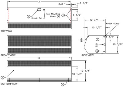
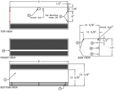
1/2
HP STANDARD UNHEATED MODELS DRAWING
|
|
|
|
|
|
NOTES: |
|
 |
|
1.
This product is designed to comply with the National
Electric Code (NEC) ETL listed for US &
Canada, and
bear the CE mark. |
|
| 2.
7/16" mounting holes (4) provided, (2) on each end. |
|
3.
1/2" key hole slots (2) provided, (1) on each end for wall
mounting. |
|
4.
All units have a self contained one piece cabinet, fire
retardant and corrosion proof pain lock metal,
double
protected with baked on gray color rust preventative
electrostatic polyurethane powder coating. |
|
5.
Cabinet has sufficient strength for fastening to wall on
both ends without intermediate support. |
|
| 6.
Internal J-Box(ex) for electrical wiring. |
|
7.
Unit is to be installed such that air flow is unobstructed.
Air discharge nozzle containing adjustable
air directional
vanes with 40° sweep front to back. |
|
8.
Optional motor control panel. Overloads are factory set.
Standard procedure is to ship panel loose for remote
mount. Can be factory mounted on either left
or right hand
side of air curtain housing. Please specify. |
|
|
|
|
9.
Circuit protection as per NEC by others. |
|
|
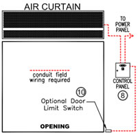
10.
Optional door limit switch is field installed and is to be
wired to the control panel. Switch
to be mounted such
that the air curtain turns on
as door begins to open. |
|
|
|
|
|
|
| -2,
-3 & -4 designates the number of motors. |
|
|
|
|
|
*NOTE:
Intake screen size and quantity varies with unit length. |
|
Model No. |
Mounting Centers A |
Length B |
|
STD2 36-1U |
35 1/8" |
36" |
|
STD2 42-1U |
41 1/8" |
42" |
|
STD2 48-1U |
47 1/8" |
48" |
|
STD2 64-2U |
63 1/8" |
64" |
|
STD2 72-2U |
71 1/8" |
72" |
|
STD2 78-2U |
77 1/8" |
78" |
|
STD2 84-2U |
83 1/8" |
84" |
|
STD2 96-2U |
95 1/8" |
96" |
|
STD2 96-3U |
95 1/8" |
96" |
|
STD2 108-2U |
107 1/8" |
108" |
|
STD2 108-3U |
107 1/8" |
108" |
|
STD2 120-3U |
119 1/8" |
120" |
|
STD2 144-3U |
143 1/8" |
144" |
|
STD2 144-4U |
143 1/8" |
144" |
|
|
|
|
|
|
|
 |
|
TYPICAL
INSTALLATION
|
|
|
1.
Connect supply voltage
from power panel to control
panel. (9) |
|
|
2.
Connect wires from motor
leads in junction box to
terminals in panel per print. |
|
|
3.
Connect wires from door
limit switch to terminals in
panel per print. |
|
|
4.
Check rotation of motors
and switch leads if
necessary to correct. |
|
|
|
|
|
|
|
|
|
|
|
1
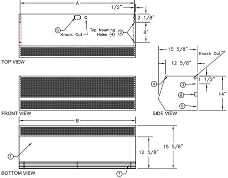
HP HIGH VELOCITY UNHEATED MODELS DRAWING
|
|
|
|
 |
|
NOTES: |
|
1.
This product is designed to comply with the
National Electric Code (NEC) ETL listed for
US
& Canada, and bear the CE mark. |
|
2.
7/16" mounting holes (4) provided, (2) on each end. |
|
3.
1/2" key hole slots (2) provided, (1) on each
end for wall mounting. |
|
4.
All units have a self contained one piece cabinet,
fire retardant and corrosion proof paint
lock metal,
double protected with baked on gray color
rust
preventative electrostatic polyurethane powder
coating. |
|
5.
Cabinet has sufficient strength for fastening to
wall on both ends without intermediate support. |
|
6.
Internal J-Box(es) for electrical wiring. |
|
7.
Units is to be installed such that air flow is
unobstructed. Air discharge nozzle containing
adjustable air directional vanes with 40°
sweep
front to back. |
|
8.
Optional motor control panel. Overloads are
factory pre-set. Standard procedure is to
ship
panel loose for remote mount. Can be factory
mounted on either left or right hand side
of air
curtain housing. Please specify. |
|
9.
Circuit protection as per NEC by others. |
|
|
|
|
10.
Optional door limit switch is field installed and
is to be wired to the control
panel. Switch to be
mounted such that the air curtain turns on
as
door begins to open. |
|
|
|
|
|
|
|
|
|
|
| -2
& -3 designates the number of motors. |
|
|
|
|
|
|
|
|
|
*NOTE:
Intake screen size and quantity varies with unit length. |
|
Model No. |
Mounting
Centers A |
Overall
Length B |
| HV236-1U |
35
1/8" |
36" |
|
HV242-1U |
41 1/8" |
42" |
|
HV248-1U |
47 1/8" |
48" |
|
HV260-1U |
59 1/8" |
60" |
|
HV272-2U |
71 1/8" |
72" |
|
HV284-2U |
83 1/8" |
84" |
|
HV296-2U |
95 1/8" |
96" |
|
HV296-3U |
95 1/8" |
96" |
|
HV2108-2U |
107 1/8" |
108" |
|
HV2108-3U |
107 1/8" |
108" |
|
HV2120-2U |
119 1/8" |
120" |
|
HV2120-3U |
119 1/8" |
120" |
|
HV2144-3U |
143 1/8 |
144" |
|
HV2144-4U |
143 1/8 |
144" |
|
|
|
|
|
|
|
|
|
|
|
|
|
|
|
|
|
|
TYPICAL
INSTALLATION
|
|
|
|
1.
Connect supply voltage
from power panel to
control panel. (9) |
|
|
|
2.
Connect wires from
motor leads in junction
box to terminals in panel
per print. |
|
|
|
3.
Connect wires from
micro switch to terminals
in panel per print. |
|
|
|
4.
Check rotation of motors
and switch leads if
necessary to correct. |
|
|
|
|
|
|
|
|
|
|
|
|
|
|
|
3
HP EXTRA POWER UNHEATED MODELS
|
|
|
|
 |
|
NOTES: |
|
1.
This product is designed to comply with the
National Electric Code (NEC) ETL listed for
US
& Canada, and bear the CE mark. |
|
2.
7/16" mounting holes (4) provided, (2) on each
end. |
|
3.
1/2" key hole slots (2) provided, (1) on each
end for wall mounting. |
|
4.
All units have a self contained one piece cabinet,
fire retardant and corrosion proof
paint lock metal,
double protected with baked on gray
color rust
preventative electrostatic polyurethane
powder
coating. |
|
5.
Cabinet has sufficient strength for fastening to
wall on both ends without intermediate support. |
|
6.
Internal J-Box(es) for electrical wiring. |
|
7.
Units is to be installed such that air flow is
unobstructed. Air discharge nozzle containing
adjustable air directional vanes with 40°
sweep
front to back. |
|
8.
Optional motor control panel. Overloads are
factory set. Standard procedure is to ship
panel loose for remote mount. Can be factory
mounted on either left or right hand side
of air
curtain housing. Please specify. |
|
|
|
|
9.
Circuit protection as per NEC by others. |
|
|
10.
Optional door limit switch is field installed
and is to be wired to the control
panel. Switch
to be mounted such that the air
curtain turns
on as door begins to open. |
|
|
11.
EP2 units with 115V motors will have an intake
screen with hole pattern in a
narrower region
(8 1/2" x dimenstion B) of the
intake face area. |
|
|
|
|
|
|
| -2
& -3 designates the number of motors. |
|
|
|
|
|
|
|
*NOTE:
Intake screen size and quantity varies with unit length. |
MODEL
NUMBER |
MOUNTING
CENTERS A |
OVERALL
LENGTH B |
| EP236-1U |
35
1/8" |
36" |
|
EP248-1U |
47 1/8" |
48" |
|
EP260-1U |
59 1/8" |
60" |
|
EP272-2U |
71 1/8" |
72" |
|
EP284-2U |
83 1/8" |
84" |
|
EP296-2U |
95 1/8" |
96" |
|
EP2108-2U |
107 1/8" |
108" |
|
EP2108-3U |
107 1/8" |
108" |
|
EP2120-2U |
119 1/8" |
120" |
|
EP2120-3U |
119 1/8" |
120" |
|
EP2144-3U |
143 1/8" |
144" |
|
|
|
|
|
|
|
|
|
|
|
|
TYPICAL
INSTALLATION
|
|
|
|
1.
Connect supply voltage
from power panel to control
panel. (9) |
|
|
|
2.
Connect wires from motor
leads in junction box to
terminals in panel per print. |
|
|
|
3.
Connect wires from micro
switch to terminals in panel
per print. |
|
|
|
4.
Check rotation of motors
and switch leads if necessary
to correct. |
|
|
|
|
|
|
|
|
|
|
|
|
|
|
|
|
|
|
|
|
|
|
TYPICAL
INSTALLATION OF METAL AIR CURTAINS
FOR DRUM TYPE ROLL-UP DOORS
|
|
 |
|
|
TYPICAL
INSTALLATION FOR VERTICAL LIFT TRACK DOORS
|
|
 |
|
|
|
TYPICAL
INSTALLATION FOR OVERHEAD MOUNTING
|
|
|
|
|
 |
|
|
Air Curtain,
Air Curtain Door, Air Curtain Heater, Air Curtains, Air Doors,
Door Air Curtains, Heat Curtains, Mars Air Curtain,
Mars Air Door, Warm Air Curtains, and Insect Barrier from
your source for material handling equipment.
|
Back to Product Page
|
| HOME /
ORDER / SEARCH
/
QUOTE /
CONTACT US / ABOUT
US /
MY ACCOUNT/
SHOPPING CART |
|