Back to Product Page
|
|
|
|
|
|
|
|
|
|
CONDUCTOR
BAR SELECTION
|
|
|
|
|
| Determining
Ampere Load |
|
|
|
|
The
conductor selected must be large enough to carry the
necessary ampere load safely without undue heating. To
compute the ampere load, proceed as follows: |
|
Heavy
Duty — Class D Crane Service Used continually
during the work day and usually for more than one shift.
Loads of 50% of rated capacity or more handled constantly
during the work period. Use a factor of 110% of the
calculated ampere load. |
1.
List the horsepower of all motors used in the
application. |
|
2.
Determine the voltage and type of current that will feed
the conductor. For example: 230v dc 2 wire;
460v ac 3
phase; etc. |
|
Severe
Duty — Class E and F Crane Service Handles
loads approaching 100% of the capacity all during the work
period and for more than one shift. This includes large,
heavy duty units such as bucket cranes, magnet lift cranes,
cement or steel handling cranes. Use a factor of 120% of
the calculated ampere load. Check the traveling speed of
the crane, as it may exceed the tracking capability of the
Figure 8 Conductor. |
3.
Refer to the Horsepower Conversion Table on page 3
and convert the horsepower to amperes. |
|
4.
Prepare the ampere load figure that will be used to size
the conductors as follows: |
|
|
List
the full load ampere rating of each motor used
on the crane or monorail unit. Determine the duty
cycle from the following paragraphs and apply the
corresponding factor. |
|
|
|
5.
If the conductors are to be located where the ambient
air temperature is unusually high, the current carrying
capacity of the conductor is reduced. Multiply the current
capacity of the selected conductor by the derating factor in
the following table. |
|
Light
Duty — Class A and B Crane Service
Standby or infrequent use. Up to two motors started
at a time. Two to five lifts per hour. Use a factor of
90% of the calculated ampere load. |
|
|
|
Temperature
Derating Table |
|
|
|
Ambient Air Temperature |
Derating Factor |
| 100°F |
95% |
| 130°F |
75% |
| 160°F* |
50% |
|
|
Average
Duty — Class C Crane Service
Moderate use during the work day. Five to ten lifts
per hour. Not over 50% of the lift at rated capacity.
Use a factor of 100% of the calculated ampere load. |
|
|
|
|
|
|
|
*At
this ambient temperature it will be necessary to use the higher
rated conductor cover, XHT rated at 280° F. |
|
|
|
| Determining
Voltage Drop |
|
|
|
According
to CMAA, the voltage drop to the unit motors
shall not be more than 3% from the power taps to the load
at the farthest point on the conductor run. To determine
the voltage drop use the appropriate formula in the
following table. |
|
See
Conductor Engineering Data Table on page 4 for
values of Z and R. |
|
Divide
voltage drop by system voltage to get the percent
of voltage drop. |
|
Maximum
voltage drops that are 3% of various supply
voltages are as follows: |
|
|
|
Current Type |
Formula |
| AC 3 phase
60 cycle |
V = L x
I x Z x 1.73 |
| AC 1 or
2 phase 60 cycle |
V = L x
I x Z x 2 |
| DC 2 wire
system |
V = L x
I x R x 2 |
|
|
|
|
|
|
Supply Voltage |
Voltage Drop (V) |
| 460v ac |
13.8 |
| 230v ac
or dc |
6.9 |
| 575v ac |
17.2 |
|
|
|
| V
= Voltage drop |
|
| L
= Distance from power feed to end of conductor |
|
Volts
lost that are equal to or less than the above values
when using the formulas above will help in selecting the
correct conductor. |
I
= Total amperes drawn as calculated from
conversion charts |
|
| Z
= ac impedance |
|
|
| R
= dc resistance |
|
|
|
|
|
|
|
|
|
| Conductor
Selection Example |
|
Horsepower
Conversion Table |
Given
a 300 foot runway, power fed at the center, using
460 volt, 3 phase, 60 cycle power supplied to a bridge
crane — there is a 40 h.p. hoist motor, a 20 h.p. bridge
motor, and a 5 h.p. trolley motor. The operation is Average
Duty. Ambient temperature varies from 50°F in winter to
90°F in summer on this Indoor installation. |
|
|
3
Phase AC - 60 Cycle
Amperes |
Direct
Current Amperes |
|
H.P. |
230v |
460v |
575v |
230v |
|
1/2 |
2 |
1 |
0.8 |
2.7 |
|
3/4 |
2.8 |
1.4 |
1.1 |
3.8 |
|
1 |
3.6 |
1.8 |
1.4 |
4.7 |
|
1 1/2 |
5.2 |
2.6 |
2.1 |
6.6 |
|
2 |
6.8 |
3.4 |
2.7 |
8.5 |
|
3 |
9.6 |
4.8 |
3.9 |
12.2 |
|
5 |
15.2 |
7.6 |
6.1 |
20 |
|
7 1/2 |
22 |
11 |
9 |
29 |
|
10 |
28 |
14 |
11 |
38 |
|
15 |
42 |
21 |
17 |
55 |
|
20 |
54 |
27 |
22 |
72 |
|
25 |
68 |
34 |
27 |
89 |
|
30 |
80 |
40 |
32 |
106 |
|
40 |
104 |
52 |
41 |
140 |
|
50 |
130 |
65 |
52 |
173 |
|
60 |
154 |
77 |
62 |
206 |
|
75 |
192 |
96 |
77 |
255 |
|
100 |
248 |
124 |
99 |
341 |
|
125 |
312 |
156 |
125 |
425 |
|
150 |
360 |
180 |
144 |
506 |
|
200 |
480 |
240 |
192 |
675 |
|
| Step
1 - Determining Ampere Load |
|
See
National Electric Code article 610-14(e)for
determining motor loads where there are multiple motors
on a single crane. Then from the Horse Power Conversion
Table 460v column (right): |
|
|
40
h.p. hoist motor — 52 amps @ 100% = 52 amps |
|
|
|
20
h.p. bridge motor — 27 amps @ 50% = 13.5 amps |
|
|
5
h.p. trolley motor — 7.6 amps @ 50% = 3.8 amps |
|
|
The
total current load is 69.3 amperes. |
|
|
With
Average Duty cycle, the current load is
factored at 100%. Normal ambient conditions of
50°F to 90°F require no temperature derating.
Selecting a 90 amp conductor caused a voltage
drop of 4.3% using the formula. Since this is
unsatisfactory, use a 110 amp conductor (FE-908)
for Step 2. |
|
| Step
2 - Determining Voltage Drop |
|
| Use
the AC 3 phase formula above. |
|
|
V
= L x I x Z x 1.73 where: |
|
|
L
= 150 ft. (Distance to the end of the runway from
the center power feed.) |
|
|
I
= 69.3 amperes |
|
|
Z
= .0008 for 110 amp conductor |
|
|
1.73
= 3 phase constant |
|
|
V
= 150 x 69.3 x .0008 x 1.73 |
|
|
|
=
14.4 volts |
|
|
|
|
|
|
|
|
|
|
|
|
|
|
|
|
|
|
14.4/460
= 3.1%
|
|
|
|
Since
this voltage drop only occurs at the farthest end
when two or more motors are started simultaneously,
exceeding the 3% voltage drop goal by only 0.1% will not
cause a problem. |
|
|
|
|
|
|
| Ampere
Load Calculations for Multiple Units |
|
The
voltages listed are rated motor voltages. The current
listed shall be permitted for system voltage ranges of 110
to 120, 220 to 240, 440 to 480, and 550 to 600 volts.
Motors rated at 208v ac should increase the 230 volt
column figures by 10%. |
For
information about sizing ampere loads for multiple
cranes on the same runway, see Article 610-14 (e) of the
National Electrical Code for the demand factors. This
article also covers additional loads on the bridge cranes
other than motor loads. |
|
|
For
motors that are wound for single or double phase
operation, use the nameplate rating. For older slip ring
motors or models that have secondary windings be sure to
obtain both primary and secondary current ratings.
Secondary windings may also need separate conductors
or cables when updating the electrification. |
| Induction
Type Squirrel Cage and Wound Rotor Motors |
The
Horsepower Conversion Table is taken from the 1996
NEC Article 430. The values are for motors running at
usual speeds with normal torque characteristics. Motors
built for especially low speeds or high torques may require
more running current, and multi-speed motors will have full-load
current varying with speed. In these cases, use
the higher nameplate current rating. |
|
|
|
|
|
Conductor
Engineering Data Table
|
|
Conductor Bar No. |
Description |
Weight per 10' section lbs. |
Ampere
Rating |
Coefficient of Linear Expansion per °F |
Resistance
Factor |
Circular Mills |
|
AC (z) ohms/ft. |
DC (R) ohms/ft. |
|
Continuous |
Intermittent* |
|
FE-908 |
Galvanized Steel |
6.5 |
110 |
165 |
0.000007 |
0.0008 |
0.0005 |
189,000 |
|
FE-1608 |
Stainless/Copper Laminate |
6.5 |
160 |
240 |
0.000008 |
0.000144 |
0.0001 |
188,000 |
|
FE-2008 |
Copper/Steel Laminate |
6.25 |
250 |
350 |
0.000008 |
0.000142 |
0.0001 |
189,000 |
|
FE-3008 |
Rolled Copper |
6.75 |
350 |
530 |
0.000009 |
0.000085 |
0.000058 |
188,000 |
|
FE-5008 |
Extruded Copper |
11.5 |
500 |
750 |
0.000009 |
0.000065 |
0.000033 |
315,000 |
|
| *Intermittent
Service Rating is determined for one minute on, one minute off
operation. |
| Miscellaneous
Applications |
|
|
|
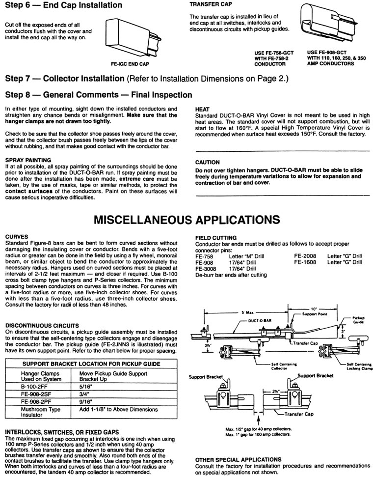
| Curves |
|
The
minimum spacing between conductors on curves is
three inches. |
Duct-O-Bars,
except the Totally Enclosed System,
can be bent to form curved sections without damaging
the insulating cover or conductor. Bends with a five-
foot radius or greater can be done in the field by using
a fly wheel, monorail beam, or similar object to bend
the conductor to approximately the necessary radius.
Hangers used on curved sections must be placed at
intervals of 2-1/2 feet maximum— and closer if required.
Use B-100 cross bolt clamp type hangers and P-Series
collectors. |
|
|
For
curves of five-foot radius or more, use five-inch
collector shoes. For curves of less than five-foot radius
use three-inch collector shoes; also consult the factory for
additional information. |
|
|
|
|
 |
| Discontinue
Circuits |
|
On
discontinuous circuits a pickup guide assembly must
be installed to ensure that the self-centering type collectors
engage and disengage the conductor bar. The pickup
guide (FE-2JNN3 is illustrated) must have its own support
point. |
|
|
| Interlocks,
Switches, or Fixed Gaps |
|
|
The
maximum fixed gap occurring at interlocks is one-inch
when using 100 amp P-Series collectors and 1/2 inch
when using 40 amp collectors. Use transfer caps as shown
to ensure that the collector brushes transfer evenly and
smoothly. Also round both ends of the contact brushes to
facilitate the transfer. Use clamp type hangers only. When
both interlocks and curves of less than a four-foot radius
are encountered, the tandem 40 amp collector is
recommended. |
 |
| Other
Special Applications |
|
|
|
Consult
the factory for recommendations on applications
such as de-icing systems, totally enclosed systems, and
other systems not covered here. |
|
|
|
|
|
|
|
|
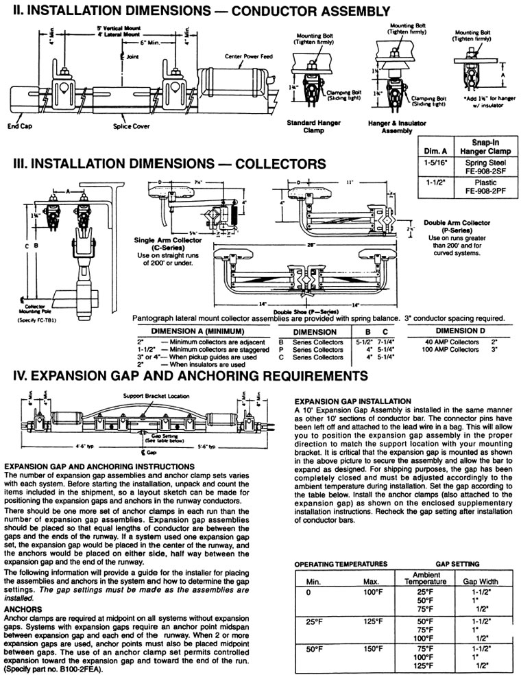
| Expansion
Gaps |
|
|
|
|
|
Expansion
gaps should be placed at intervals determined
by 1) the expansion rate of the metal in the conductor
selected, and 2) the variation in temperature that will
occur at the conductor location over a full year of operation. |
Example:
A 300' long copper conductor system (X)
installed outdoors with an anticipated temperature
fluctuation of 80°F (Y). |
|
Total
Expansion = 300'/100' x 80°F/100°F = 2.4". |
| 1.
Steel Conductor Systems |
|
3.
Determine the Number of Expansion Gap
Assemblies |
Given
that steel conductors expand 1" for every 150' of
runway with a temperature change of 100°F over a full
year of operation, put the length of the runway and the
maximum temperature change for the system to be used
into the following formula: |
|
After
calculating the actual expansion of the runway
conductor system, use the following rule of thumb to pick
the number of expansion gap assemblies: |
|
a.
Under 1" of expansion, use no expansion assemblies.
Install one anchor clamp set at the
center of the
conductor run. |
|
Total
Steel Expansion (inches) = X/150' x Y/100°F |
|
where
X is the runway length and Y is the 12 month
temperature variation. |
|
b.
From 1" to 2" of expansion, use one expansion
assembly in the center of the conductor
run. |
Example:
A 450' long steel conductor (X) installed in a
building with an indoor temperature change of 40°F (Y). |
|
c.
From 2" to 4" of expansion, use two expansion
assemblies. Locate them at 1/3 of the runway length in
from each end. |
|
Total
Expansion = 450'/150' x 40°F/100°F = 1.2". |
|
| 2.
Copper Conductor Systems |
|
d.
For systems with more than 4" of expansion, use one
expansion gap assembly for each 2" of expansion. |
Given
that copper conductors expand 1" for every 100' of
runway over a 100°F temperature change at the conductor
over a full year of operation, put the length of the runway
and the maximum temperature change for the system to
be used into the following formula: |
|
|
4.
Anchors |
|
Anchor
clamps are required at midpoint on all systems
without expansion gaps and halfway between gaps and
from gaps to the end of systems with multiple gaps. See
the Figure 8 Installation Instructions on anchor locations. |
|
Total
Copper Expansion (inches) = X/100' x Y/100°F. |
|
 |
|
The
maximum gap opening for all ten foot Figure 8
expansion gap assemblies is 1-3/4 inches. |
|
Expansion
assemblies are also required at building
expansion joints. |
|
|
|
|
|
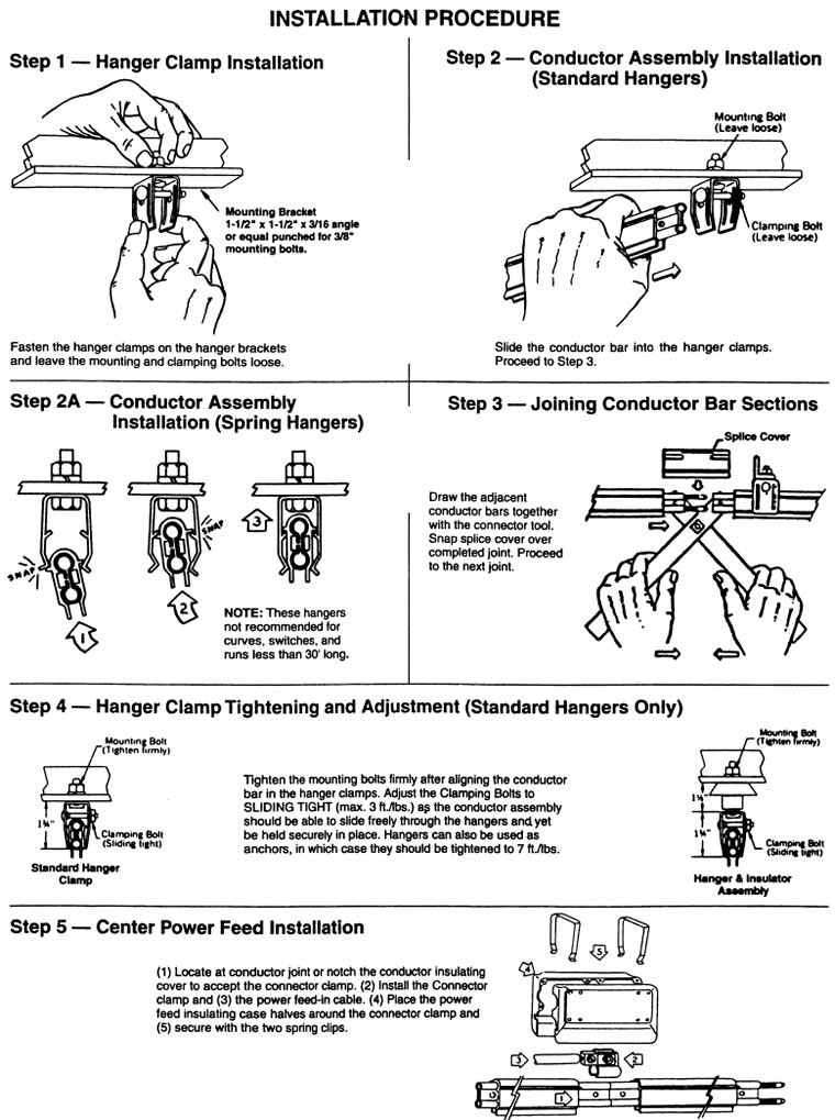
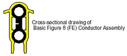
| Conductor
Assembly Selection |
|
Duct-O-Wire
Figure 8 Conductor Bars are furnished as assemblies consisting
of a ten-foot long conductor bar rated at
600 volts, an insulating cover, splice cover, and connector
pins or joint clamps as applicable. |
The
insulating cover must be appropriate for the environment —
indoor, outdoor, or high temperature — in
which the conductor is to operate. |
Indoor
systems are for use in ambient temperatures up to 160°F.
They have an Orange PVC Insulating Cover. They
are not recommended for outdoor use in direct sunlight. |
Outdoor
systems are for use in direct sunlight and ambient temperatures
up to 160°F. They have a Gray PVC
Insulating Cover with an ultraviolet additive. |
High
temperature systems are for use in ambient temperatures up to
280°F. They have a Yellow Lexan Insulating
Cover. |
From
the table to the right, you can select the basic (FE) conductor
assembly with the appropriate bar and insulating
cover for your application. |
|
|
 |
|
Order
Online, by Phone, or by E-Mail |
|
|
|
~
Add items to your online shopping cart ~
Click the Model No. of the item
you wish to purchase.
|
|
|
| Pricing
for Basic Figure 8 (FE) Conductor Assemblies (10' Lengths) |
|
|
|
|
 |
|
|
|
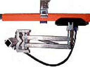
| Typical
Conductor Mounting |
|
|
|
|
|
|
|
|
|
|
|
|
| Note: |
|
indicates
minimum conductor spacing. |
|
|
|
|
|
|
 |
|
|
|
|
|
|
|
|
|
|
|
|
|
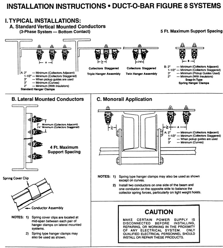
| Standard
Vertical Mounted Conductors |
|
Lateral
Mounted Conductors |
|
| 3-Phase
System • Bottom Contact • 5 Ft. Maximum Support Spacing |
|
4
Ft. Maximum Support Spacing. |
|
|
 |
|
|
Use
only Lateral (L) Model Collectors. |
|
|
|
|
|
|
 |
|
|
|
|
|
|
|
|
|
|
| Monorail
Application |
|
|
Install
two conductors on one side of the beam and one conductor
on the opposite side to balance the collector spring forces,
particularly
on light weight hoists. |
|
|
|
|
 |
|
|
|
|
|
|
Order
Online, by Phone, or by E-Mail |
|
|
|
~
Add items to your online shopping cart ~
Click the Model No. of the item
you wish to purchase.
|
|
|
|
|
|
|
|
| DUCT-O-BAR
FIGURE 8 (FE) COMPONENTS |
|
|
 |
Model Number |
Weight
Pounds |
Description |
Price |
|
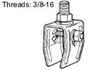
Angle
Brackets for Web Mounting
|
|
Brackets
are galvanized 12 gauge rolled steel channel.
Hangers are priced separately, but will be factory installed
at no charge
when hanger locations are shown on sketch.
|
|
B-100-BR1A |
1 |
Bracket - 11-1/4" long. |
$6.20
|
|
|
1.12 |
Bracket - 14-1/4" long. |
$8.40
|
|
|
1.18 |
Bracket with gusset support - 14-1/4" long. |
$10.00
|
|
|
1.5 |
Bracket - 20-1/4" long. |
$11.20
|
|
|
1.57 |
Bracket with gusset support - 20-1/4" long. |
$12.80
|
|
|
|
|
Model Number |
Weight
Pounds |
Description |
Price |
 |
Straight
Brackets for Top Flange Mounting
|
|
Brackets
are galvanized 12 gauge rolled steel channel. Hangers
are priced
separately, but will be factory installed at no charge
when hanger locations are
shown on sketch.
|
|
B-100-BR3A |
1.25 |
Bracket - 18" long. |
$7.30
|
|
|
1.82
|
Bracket
with two Mounting Clamps
and hardware - 18" long
|
$14.50
|
|
|
1.32
|
Bracket
- 21" long
|
$8.40
|
|
|
2.01
|
Bracket
with two Mounting Clamps
and hardware - 21" long
|
$15.60
|
|
|
1.6
|
Bracket
- 24" long
|
$9.50
|
|
|
2.19
|
Bracket
with two Mounting Clamps
and hardware - 24" long
|
$16.70
|
|
|
8
|
Channel
- 10 feet long
|
$45.00
|
|
|
0.31
|
Universal
Mounting Clamps with hardware.
For 5/8" to 1-5/16" thick Beam Flanges.
|
$3.40
|
|
|
1.75
|
Capped
I-Beam Bracket with hardware. 18" long
|
$14.50
|
|
|
1.94
|
Capped
I-Beam Bracket with hardware. 21" long
|
$15.60
|
|
|
2.12
|
Capped
I-Beam Bracket with hardware. 24" long
|
$16.70
|
|
|
T-Brackets with Mounting Plate for Web Mounting |
 |
Brackets
are primed 12 gauge rolled steel channel with mounting
plate
and hardware. Hangers are priced separately, but will
be factory installed at
no charge when hanger locations are shown on sketch.
|
|
B-100-BRCT1 |
1.2 |
Bracket - 2 holes - 3-3/4" long. |
$13.00
|
|
|
1.3 |
Bracket - 3 holes - 5-1/4" long. |
$13.50
|
|
|
1.5 |
Bracket - 4 holes - 6-3/4" long. |
$14.00
|
|
|
1.6 |
Bracket - 5 holes - 8-1/4" long. |
$14.50
|
|
|
1.7 |
Bracket - 6 holes - 9-3/4" long. |
$15.00
|
|
|
1.8 |
Bracket - 7 holes - 11-1/4" long. |
$15.50
|
|
|
1.9 |
Bracket - 8 holes - 12-3/4" long. |
$16.00
|
|
|
2 |
Bracket - 9 holes - 14-1/4" long. |
$16.50
|
|
|
2.1 |
Bracket - 10 holes - 15-3/4" long. |
$17.00
|
|
|
2.2 |
Bracket - 11 holes - 17-1/4" long. |
$17.50
|
|
|
2.3 |
Bracket - 12 holes - 18-3/4" long. |
$18.00
|
|
|
Z-Brackets for Lateral Mounted Conductors |
 |
Brackets
are red primed 10 gage steel. Hangers are priced separately,
but will
be factory installed at no charge when hanger locations
are shown on sketch.
|
|
|
1.64
|
Z-Bracket
- 3" hanger spacing,
6" mounting hole spacing. O.A.L. - 7-1/2"
|
$20.00
|
|
|
1.8
|
Z-Bracket
with hardware - 3" hanger spacing,
6" mounting hole spacing. O.A.L. - 7-1/2"
|
$20.60
|
|
|
|
|
|
Order
Online, by Phone, or by E-Mail |
|
|
|
~
Add items to your online shopping cart ~
Click the Model No. of the item
you wish to purchase.
|
|
|
|
|
Model Number |
Weight
Pounds |
Description |
Price |
 |
Snap-In Type Hanger Assemblies
|
|
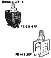
FE-908-2PF |
0.1 |
These hangers are not recommended for curves, switches
or short runs
unless separate anchors are used. Refer to the Figure
8 installation
Instructions.
|
|
Nylon Insulating Hanger. |
$1.70
|
|
FE-908-2PFS |
0.1 |
Nylon Insulating Hanger with Stainless Steel
Hardware. |
$3.40
|
|
FE-908-2SF |
0.11 |
DO NOT USE nylon hangers
in temperatures higher than
230°F. DO NOT exceed 4 lb. per foot torque when tightening
nut on mounting bolt.
|
|
Zinc Plated Steel Hanger. |
$1.70
|
|
|
Snap-In Type Spring Hanger and Insulator
Assemblies for Outdoor, Wet and Dirty Applications |
|
|
0.2
|
Zinc
Plated Steel Hanger with Insulator
|
$4.90
|
|
|
0.2
|
Epoxy
Coated Steel Hanger with Insulator
|
$6.00
|
|
|
0.2
|
Stainless
Steel Hanger with Insulator and Stainless Steel Hardware
|
$9.40
|
|
|
Clamp Type Hanger Assemblies for All Conductor Systems |
|
|
0.19
|
Zinc
Plated Steel Hanger
|
$2.50
|
|
|
Clamp Type Hanger and Insulator Assemblies
for Outdoor, Wet and Dirty Applications |
|
|
0.3
|
Zinc
Plated Steel Hanger with Insulator.
|
$6.00
|
|
|
0.3
|
Epoxy
Coated Steel Hanger with Insulator.
|
$7.70
|
|
|
0.3
|
Stainless
Steel Hanger with StainlessSteel Hardware.
|
$10.50
|
|
|
Snap-In Type Special Hanger Assemblies |
|
|
0.5
|
Plastic
Triple Hanger Assembly
|
$7.40
|
|
|
0.53
|
Zinc
Plated Steel Triple Hanger Assembly
|
$7.50
|
|
|
0.72
|
Zinc
Plated Steel Four-Gang Hanger Assembly
|
$10.40
|
|
|
0.93
|
Zinc
Plated Steel Five-Gang Hanger Assembly
|
$10.60
|
|
|
|
|
|
Order
Online, by Phone, or by E-Mail |
|
|
|
~
Add items to your online shopping cart ~
Click the Model No. of the item
you wish to purchase.
|
|
|
|
|
Model Number |
Weight
Pounds |
Description |
Price |
|
|
Power
Feeds with Insulating Case
|
|
|
0.26
|
110
Amp Rated - Copper. For FE-908-2 systems.
Will accept up to #2 AWG cable.
|
$13.40
|
|
|
0.63
|
250
Amp Rated - Bronze.For FE-1608-2 and FE-2008-2 systems.
Will accept up to #1/0 AWG cable.
|
$38.90
|
|
|
1.1
|
350
Amp Rated - Cast Bronze. For FE-3008-2
systems. Will accept up to #3/0 cable.
|
$58.00
|
|
|
End Power Feeds |
|
|
0.14
|
40
Amp Rated. For all systems with FE-908,
FE-1608, FE-2008, and FE-3008 conductor bar.
|
$8.40
|
|
|
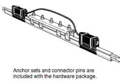
Expansion Gap Assemblies |
|
Each assembly consists of a ten-foot conductor bar,
insulating cover, connector pins for one end, guide
assembly,
two power feeds with a jumper cable and hanger set.
Refer
to the Figure 8 Installation Instructions.
|
|
|
9
|
For
Indoor System FE-908-2.
|
$134.00
|
|
|
9
|
For
Outdoor System FE-908-2-SC.
|
$140.00
|
|
|
9
|
For
High Temperature System FE-908-2XHT.
|
$145.00
|
|
|
10.5
|
For
Indoor System FE-1608-2.
|
$334.00
|
|
|
10.5
|
For
Outdoor System FE-1608-2-SC.
|
$350.00
|
|
|
10.5
|
For
High Temperature System FE-1608-2XHT.
|
$360.00
|
|
|
10
|
For
Indoor System FE-2008-2.
|
$330.00
|
|
|
10
|
For
Outdoor System FE-2008-2-SC.
|
$345.00
|
|
|
10
|
For
High Temperature System FE-2008-2XHT.
|
$355.00
|
|
|
12.5
|
For
Indoor System FE-3008-2.
|
$356.00
|
|
|
12.5
|
For
Outdoor System FE-3008-2-SC.
|
$372.00
|
|
|
12.5
|
For
High Temperature System FE-3008-2XHT.
|
$378.00
|
|
|
Special Application Components |
|
|
3.75
|
Pickup
Guide Assembly - 3" wide. Includes
clamps and two foot section of system conductor.
Specify conductor system.
|
$134.00
|
|
|
|
|
|
Order
Online, by Phone, or by E-Mail |
|
|
|
~
Add items to your online shopping cart ~
Click the Model No. of the item
you wish to purchase.
|
|
|
|
|
Model Number |
Weight
Pounds |
Description |
Price |
|
|
Special
Application Components (cont.)
|
|
|
0.08
|
Transfer
Cap. For FE-908, FE-1608, FE-2008,
and FE-3008 Bar.
|
$4.50
|
|
|
0.08
|
Transfer
Cap. For FE-908, FE-1608, FE-2008 and
FE-3008 Bar. Cut at 45° for left hand curves.
|
$7.30
|
|
|
0.08
|
Transfer
Cap. For FE-908, FE-1608, FE-2008, and
FE-3008 Bar.Cut at 45° for right hand curves.
|
$7.30
|
|
|
0.02
|
Isolating
Piece - 1" long. For all bars except
FE-758 and FE-5008
|
$2.80
|
|
|
0.19
|
Isolating
Piece - 8" long. For all bars except
FE-758 and FE-5008
|
$7.80
|
|
B-100-TG
|
1.81
|
Steel
Transfer Guide Assembly.
For use with isolating pieces.
|
Upon
Request
|
|
B-100-TGE
|
1.81
|
Epoxy
Coated Transfer Guide Assembly.
For use with isolating pieces.
|
Upon
Request
|
|
|
C-Series Collector Assemblies |
|
C-Series
Collectors are used on short continuous run systems.
They feature steel pivot points for good tracking capability.
|
|
C-40-V3 |
1.5 |
40 Amp Collector - single shoe.
Vertical mount. |
$67.00
|
|
|
2.75
|
40
Amp Collector - single shoe. Lateral mount
with steel counter weight. O.A.L. - 15"
|
$78.00
|
|
|
1.8
|
100
Amp Collector - single shoe. Vertical mount.
|
$82.50
|
|
|
3.13
|
100
Amp Collector - single shoe. Lateral mount
with steel counter weight. O.A.L. - 16"
|
$100.00
|
|
|
|
|
Collector Mounting Post |
|
|
3.25
|
Mounting
Post with Hardware - 18" long.
Mounting plate is 4" square with 3" hole
spacing for C-Series and P-Series Collectors.
(Contact us for special lengths or finishes.)
|
$49.50
|
|
|
P-Series Collector Assemblies |
|
P-Series
collectors are used on straight and curved runs and
transfers.
The pantograph design provides virtually constant spring
pressure for the
entire stroke range. Lateral Mount Collectors are provided
with spring balance.
Conductor Bars must be spaced at least 3 inches apart.
|
|
P-40-V3 |
2.19 |
40 Amp Collector - single shoe. Vertical mount. |
$72.50
|
|
|
2.5
|
40
Amp Collector - single shoe. Lateral mount.
|
$78.00
|
|
|
2.25
|
40
Amp Collector - single shoe. Self-centering.
|
$94.50
|
|
|
2.44
|
100
Amp Collector - single shoe. Vertical mount.
|
$88.00
|
|
|
2.55
|
100
Amp Collector - single shoe. Lateral mount.
|
$99.00
|
|
|
2.6
|
100
Amp Collector - single shoe. Self-centering.
|
$110.00
|
|
|
|
|
|
Order
Online, by Phone, or by E-Mail |
|
|
|
~
Add items to your online shopping cart ~
Click the Model No. of the item
you wish to purchase.
|
|
|
|
|
Model Number |
Wgt.
Lbs. |
Description |
Price |
|
|
P-80-VT3 |
4.34 |
P-Series
Collector Assemblies (cont.)
|
80 Amp Collector - double shoe.
Vertical mount. |
$131.00
|
|
|
4.35
|
80
Amp Collector - double shoe.
Lateral mount.
|
$143.00
|
|
|
4.5
|
80
Amp Collector - double shoe.
Self-centering.
|
$154.00
|
|
|
5
|
200
Amp Collector - double shoe.
Vertical mount.
|
$160.00
|
|
|
4.63
|
200
Amp Collector - double shoe.
Lateral mount.
|
$171.00
|
|
|
4.6
|
200
Amp Collector - double shoe.
Self-centering.
|
$194.00
|
|
|
Additional Components |
|
|
0.03
|
Spring
Cover Clip - Zinc Plated Steel.
Used only to ensure alignment of the
cover on laterally mounted systems.
Placed midway between hangers.
|
$1.20
|
|
|
0.3
|
Clamp
Hanger Set - 2 pieces.
Clamps both sides of hanger.
|
$6.70
|
|
|
0.04
|
Flexible
PVC End Cap.
For all Figure 8 conductor bars.
|
$1.20
|
|
|
2.88
|
Connector
Tool. One tool usually ordered
for each new system. Used to pull two
sections of bar together.
|
$22.20
|
|
|
0.1
|
Connector
Tool Pins - Pair.
|
$5.60
|
|
|
0.05
|
Splice
Cover - Standard black. Use this part number when ordering
extra splice covers.
|
$1.20
|
|
|
Conductor
Bar Cleaning Accessories |
|
C-100-VCT |
1.8 |
Contact
us for application.
|
Complete C-Series Collector with
cleaning head. Vertical mount. |
$93.50
|
|
|
2.19
|
Complete
P-Series Collector with cleaning head. Vertical mount.
|
$99.00
|
|
|
0.17
|
Series
C & P Contact Shoe with
Self Cleaning Inserts - 3"L x 1/4"W
|
$20.00
|
|
|
0.26
|
Series
C & P Contact Shoe with
Self Cleaning Inserts - 5"L x 1/4"W
|
$31.10
|
|
|
0.14
|
Cleaning
Brush - Stainless Steel.
|
$37.80
|
|
|
|
|
DUCT-O-BAR
|
|
|
|
|
|
|
SPECIAL
APPLICATION CONDUCTORS
|
|
|
|
|
|
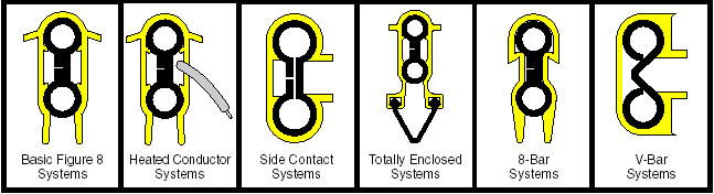
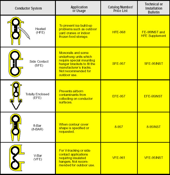
All
Duct-O-Wire Figure 8 conductor systems can be sized electrically
by using the general and technical
information contained in this brochure. For applications with
special mechanical or environmental considerations,
refer to the table below for the proper Duct-O-Bar System to
use. |
|
|
|
|
|
|
 |
|
|
| PRICE
UPON REQUEST |
|
Conductor Systems,
Duct-O-Wire Festoon Electrification, Conductor Bar, Duct-O-Wire,
and Duct-O-Bar from your
complete source for material handling equipment.
|
Back to Product Page
|
| HOME /
ORDER / SEARCH
/
QUOTE /
CONTACT US / ABOUT
US /
MY ACCOUNT/
SHOPPING CART |
|