Back to Product Page
COMMERCIAL
High Performance 10
|
AIR
CURTAINS (AMBIENT, UNHEATED)
|
|
| Designed
to meet the functional needs of the application and to integrate
into the space. |
|
|
|
|
|
 |
|
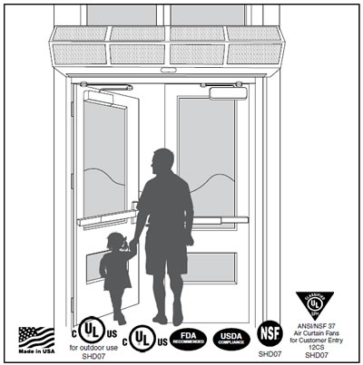
For
mounting heights to 10' (environmental separation) and
8' (insect control). |
|
|
|
|
|
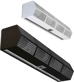
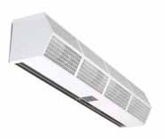
Available
in single lengths from 3' to 10'. Simple design, high performance,
white or black powder-coated exterior. |
|
|
|
|
|
Custom
colors or stainless steel (Grade 304 or better) available
(call us for more info). |
|
|
|
|
|
•
AMCA certified ambient & electric heated models
• Designed to meet the functional needs of the application
and to
integrate into the space
• Meets IECC building code which allows AMCA certified
air
curtains as an alternative to vestibules
• Simple to install, operate, and maintain
• Made in U.S.A |
|
|
|
|
|
Series
#CHD10A
|
|
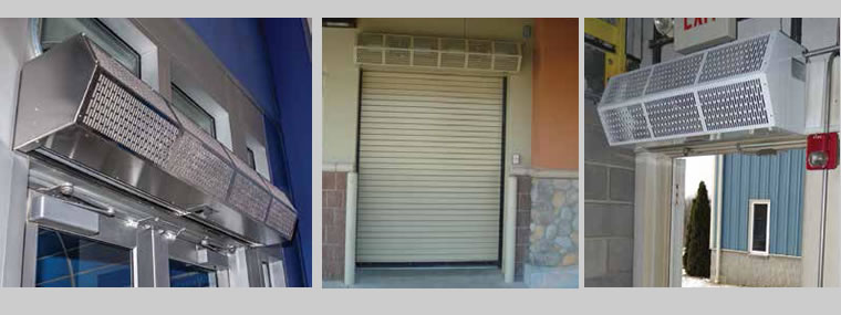
IDEAL
APPLICATIONS: |
|
|
|
|
Service
/ Employee Doors
Main Entrances
Conveyors
Shipping & Receiving |
|
|
|
|
|
|
|
|
|
Tamper
Resistant Correctional Package Available |
|
|
|
|
|
| Standard
Construction |
|
|
Installation
& Mounting |
|
|
|
|
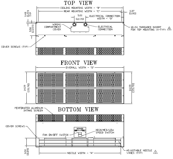
•
14” high x 15” deep
• ½ hp three-speed motor(s)
• Factory installed fan speed switch
• White or black aluminum exterior cover
• Wall and top mounting
• Optional:
3/8” aluminum filter (washable) |
|
|
|
|
|
Simple
to install, operate & maintain |
|
|
•
Single lengths up to 10’
• No Assembly Required
• 1/4” keyhole slots for wall mounting
• 5/16” threaded inserts for top mounting |
|
|
|
|
|
Optional:
Wall mounting plate |
|
|
|
|
|
|
| Control
Options |
|
|
|
|
| •
Deluxe |
|
|
|
|
|
|
|
|
 |
|
|
Ambient
(Unheated) Air Curtain Data Sheet
|
|
MODEL
|
Nozzle
Width
(in)
|
Max
Vel. at
Nozzle
(fpm)
|
Avg.
Outlet
Vel.
(fpm)
|
Air
Volume
(cfm)
|
Outlet
Vel.
Uniformity
|
Power
Rating
(kW)
|
Motor(s)
@ hp
|
Net
Wt.
(lbs)
|
|
CHD10-1036A
|
36
|
3,284
|
2,062
|
1,804
|
73%
|
0.78
|
1
@ 1/2
|
50
|
|
CHD10-1042A
|
42
|
3,592
|
1,748
|
1,784
|
54%
|
0.74
|
1
@ 1/2
|
52
|
|
CHD10-1048A
|
48
|
3,614
|
1,515
|
1,768
|
62%
|
0.75
|
1
@ 1/2
|
53
|
|
CHD10-1060A
|
60
|
3,319
|
1,184
|
1,726
|
48%
|
0.73
|
1
@ 1/2
|
54
|
|
CHD10-2060A
|
60
|
3,711
|
1,801
|
2,626
|
74%
|
1.21
|
2
@ 1/2
|
70
|
|
CHD10-2072A
|
72
|
3,284
|
2,062
|
3,608
|
73%
|
1.56
|
2
@ 1/2
|
84
|
|
CHD10-2084A
|
87
|
3,592
|
1,687
|
3,568
|
54%
|
1.49
|
2
@ 1/2
|
104
|
|
CHD10-2096A
|
99
|
3,614
|
1,470
|
3,536
|
62%
|
1.49
|
2
@ 1/2
|
106
|
|
CHD10-3096A
|
99
|
3,284
|
1,841
|
4,430
|
73%
|
1.99
|
3
@ 1/2
|
120
|
|
CHD10-2108A
|
111
|
3,319
|
1,295
|
3,494
|
48%
|
1.48
|
2
@ 1/2
|
107
|
|
CHD10-3108A
|
111
|
3,284
|
2,006
|
5,412
|
73%
|
2.34
|
3
@ 1/2
|
150
|
|
CHD10-2120A
|
116.25
|
3,319
|
1,222
|
3,452
|
48%
|
1.47
|
2
@ 1/2
|
108
|
|
CHD10-3120A
|
116.25
|
3,284
|
1,908
|
5,392
|
54%
|
2.3
|
3
@ 1/2
|
152
|
|
NOTE:
Operation at 50 Hz will generate approximately a 17% reduction
in air performance.
See Electrical Performance Sheet below for amp draws/total load
requirements. |
|
Ambient
(Unheated) Air Curtain Electrical Performance Sheet
|
|
|
120/1/60
(voltage code A)
|
208/1/60
(voltage code B)
|
240/1/60
(voltage code J)
|
|
|
MOTOR
AMP DRAW = 3.4 each
|
MOTOR
AMP DRAW = 1.7 each
|
MOTOR
AMP DRAW = 1.7 each
|
|
MODEL
#
|
#
Ckts
|
Amps
per Circuit
|
Breaker
Rating per
Circuit
|
Amps
per
Circuit
|
Breaker
Rating per
Circuit
|
Amps
per
Circuit
|
Breaker
Rating per
Circuit
|
|
CHD10-1036A
|
1
|
6.5
|
15
|
3.5
|
15
|
3.5
|
15
|
|
CHD10-1042A
|
|
CHD10-1048A
|
|
CHD10-1060A
|
|
CHD10-2060A
|
1
|
13
|
20
|
7
|
15
|
7
|
15
|
|
CHD10-2072A
|
|
CHD10-2084A
|
|
CHD10-2096A
|
|
CHD10-3096A
|
1
|
19.5
|
25
|
10.5
|
15
|
10.5
|
15
|
|
CHD10-2108A
|
|
CHD10-3108A
|
|
CHD10-2120A
|
|
CHD10-3120A
|
|
|
|
480/3/60
(voltage code Z)
|
|
MOTOR
AMP DRAW = 0.9 each
|
|
MODEL
#
|
#
Ckts
|
Amps
per Circuit
|
Breaker
Rating per Circuit
|
|
CHD10-1036A
|
1
|
1.4
|
15
|
|
CHD10-1042A
|
|
CHD10-1048A
|
|
CHD10-1060A
|
|
CHD10-2060A
|
1
|
2.8
|
15
|
|
CHD10-2072A
|
|
CHD10-2084A
|
|
CHD10-2096A
|
|
CHD10-3096A
|
1
|
4.2
|
15
|
|
CHD10-2108A
|
|
CHD10-3108A
|
|
CHD10-2120A
|
|
CHD10-3120A
|
|
|
|
CHD10
AMBIENT SYSTEM
|
|
 |
|
|
|
 |
|
|
|
NOTES: |
|
1.
Air curtain must be installed so air
stream is not obstructed when
deflected 20° to either side of C. |
|
2.
Electrical connections to be flexible. |
|
3.
Field verify dimensions. |
|
4.
Anchors to supporting structure
by others. |
|
5.
Adequacy of supporting structure
is to be verified by a professional
structural engineer. |
|
6.
Letter "A" in model number designates
electric heated unit. |
|
7.
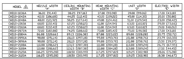
Dimensions in inches [centimeters]. |
|
|
|
|
 |
|
Order
Online, by Phone, or by E-Mail |
|
|
|
~
Add items to your online shopping cart ~
Click a Price of the item you
wish to purchase.
|
|
|
|
|
|
|
| PRICING
FOR COMMERCIAL LOW PROFILE 10 UNHEATED AIR CURTAIN |
|
MODEL
#
|
PRICES
|
SHIPPING
WEIGHT (lbs.)
|
|
120-240V
SINGLE PHASE ¹
|
480-600V
THREE PHASE ² ³
|
|
CHD10-1036A
|
|
|
64
|
|
CHD10-1042A
|
|
|
67
|
|
CHD10-1048A
|
|
|
68
|
|
CHD10-1060A
|
|
|
69
|
|
CHD10-2060A
|
|
|
90
|
|
CHD10-2072A
|
|
|
108
|
|
CHD10-2084A
|
|
|
133
|
|
CHD10-2096A
|
|
|
136
|
|
CHD10-3096A
|
|
|
154
|
|
CHD10-2108A
|
|
|
137
|
|
CHD10-3108A
|
|
|
192
|
|
CHD10-2120A
|
|
|
138
|
|
CHD10-3120A
|
|
|
195
|
|
¹
Control Voltage: 120V (control package required for 24V control).
² Control Voltage: 208V or 240V (control package required
for 24V control).
³ Control Voltage: 24V |
|
|
 |
|
Order
Online, by Phone, or by E-Mail |
|
|
|
~
Add items to your online shopping cart ~
Click the Model No. of the item
you wish to purchase.
|
|
|
|
|
|
|
|
Model
No.
|
Description
|
Price
|
|
|
Deluxe
Low Voltage Control (includes time delay relay,
24 volt control transfomer, and magentic reed door switch)
|
$398
|
|
|
|
INSTALLATION
& MAINTENANCE INSTRUCTIONS
|
|
|
|
|
|
|
|
|
 |
Commercial
High
Performance 10
Air Curtain
(Air Door) |
|
|
 |
Sanitation
Certified
High Performance 7
Air Curtain
(Air Door) |
|
|
|
|
|
|
|
|
|
|
|
|
|
|
|
|
|
 |
| TABLE
OF CONTENTS |
|
|
I.
UNCRATING
II. GENERAL MOUNTING INSTRUCTIONS
III. WALL MOUNTING
IV. SUSPENDED MOUNTING
V. ELECTRICAL CONNECTIONS
VI. FIELD CONNECTIONS
VII. OPERATING INSTRUCTIONS
VIII. MAINTENANCE AND CLEANING
IX. SERVICE |
|
WARNING:
TO REDUCE THE RISK OF FIRE, ELECTRIC SHOCK OR INJURY TO PERSONS,
OBSERVE THE FOLLOWING: |
A.
Read all instructions before installing or using this air curtain.
B. Use this unit only in the manner intended by the manufacturer
and described in this manual. Any other use not recommended
by the manufacturer may cause fire,
electric shock, or injury to persons. If you have any questions,
contact the manufacturer.
C. Before servicing or cleaning unit, switch power off at service
panel and lock the service disconnecting means to prevent power
from being switched on accidentally.
When the service disconnecting means cannot be locked, securely
fasten a prominent
warning device, such as a tag, to the
service panel.
D. Installation work and electrical wiring must be done by qualified
person(s) in accordance with all applicable national and local
codes having jurisdiction, including
fire-rated construction. See below, ELECTRICAL CONNECTIONS (NEC
Code ANSI/NFPA
No. 70).
E. When cutting or drilling into wall or ceiling, do not damage
electrical wiring and other hidden utilities.
F. To reduce the risk of fire, do not store or use gasoline
or other flammable vapors and liquids in the vicinity of the
air curtain.
G. This air curtain is hot when in use. To avoid burns, do not
let bare skin touch hot surfaces. Keep combustible materials,
such
as furniture, pillows, bedding, papers,
clothes, etc. and curtains at least 1 inch from the top, back,
front, sides and at least
6 feet from the discharge of the air
curtain.
H. Extreme caution is necessary when any air curtain is used
by or near children or invalids, and whenever the heater is
left
operating unattended.
I. Do not operate any air curtain after it malfunctions. Disconnect
power at the service panel and have the air curtain inspected
by a reputable electrician before reusing.
J. To disconnect the air curtain, turn controls to “off”,
and turn off power to the air curtain circuit at main disconnect
panel.
K. Do not insert or allow foreign objects to enter any ventilation
or discharge opening as this may cause an electric shock or
fire,
or damage the air curtain.
L. To prevent a possible fire, do not block the air intake or
discharge of the air curtain in any manner.
M. The air curtain has hot and arcing or sparking parts inside.
Do not use it in areas where gasoline, paint, or flammable vapors
or liquids are used or stored.
N. This heater may include an audible or visual alarm to warn
that parts of the heater are getting excessively hot. If the
alarm
sounds (or illuminates), immediately
turn the heater off and inspect for any objects on or adjacent
to the heater that may have
blocked the airflow or otherwise
caused high temperatures to have occurred.
DO NOT OPERATE THE HEATER WITH THE ALARM SOUNDING (OR ILLUMINATING). |
|
|
|
| I.
UNCRATING |
|
 |
Carefully
examine the carton(s) for damage. If the
carton is damaged, immediately notify the shipping
company. Do not delay in filing claim. If the air
curtain(s) were shipped on wooden skids, remove
protective wood and banding straps securing the
carton(s) to the skid. Open the carton(s) and
remove all protective packaging. |
|
|
|
Immediately
verify that the electrical rating nameplate
located on the cover matches electrical power supply
available. Retain the shipping carton(s) until the air
curtain(s) are installed and properly operating. |
|
|
|
ACCESSORIES:
If the air curtain was ordered with a wall mounting
plate, remove and save the two (2) locking screws
from the back corners and detach the wall mounting
plate. See Figure 1. |
|
|
|
|
|
|
If
the air curtain(s) were ordered with optional electrical
accessories, the accessories will be found in the carton
containing the air curtain or in a separate carton(s)
accompanying the air curtain(s). Check all of the
cartons/skids for accessories before discarding. |
|
|
|
Simple
to Install
Easy to operate & maintain |
|
 |
|
 |
|
 |
|
| II.
MOUNTING INSTRUCTIONS (General) |
|
 |
|
|
INDOOR
MOUNTING - Environmental/ Insect/Dust
Control
OUTDOOR MOUNTING (Unheated Only) - Insect/
Dust Control |
|
|
|
The
Commercial High Performance 10 & the Sanitation
Certified High Performance 7 Air Curtains are designed
to be an effective barrier against cold drafts in the winter
and hot air in the summer, flying insects and airborne
contaminants. |
|
|
|
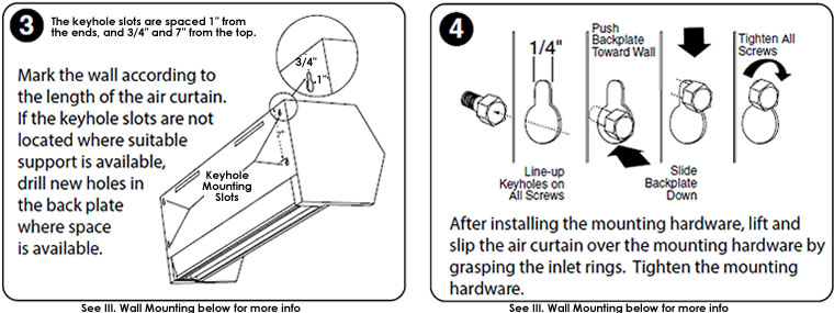
To
achieve optimum protection, the air curtain should
be mounted on the inside of the building, flush to the
wall and as close to the top of the door opening as
possible. To ensure peak performance, keep the air
stream free of obstructions. |
|
|
|
The
air curtain will not perform properly if negative air
pressure exists in the building. Under these conditions,
a means for makeup air to the building must be provided
so that the air pressure on both sides of the opening is in
balance. |
|
|
|
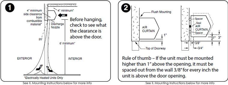
Before
mounting the air curtain, check the supporting
structure to verify that it has sufficient load-carrying
capacity to support the weight of the air curtain(s).
The mounting hardware (supplied by others) should
be capable of supporting a minimum of three (3)
times the weight of the air curtain.
See Table 1 or Table 2. |
|
|
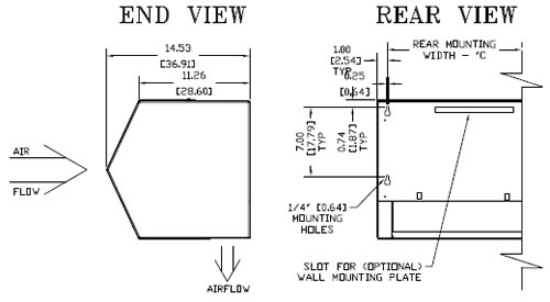
Figure
2 |
|
|
| IMPORTANT:
A minimum of 4” is required above |
|
|
Model
|
CHD08
Ambient
|
CHD08
Electric
|
Model
|
SHD07
Ambient
|
|
CHD10-1036
|
50
|
52
|
SHD07-1036
|
50
|
|
CHD10-1042
|
52
|
55
|
SHD07-1042
|
52
|
|
CHD10-1048
|
53
|
56
|
SHD07-1048
|
53
|
|
CHD10-1060
|
54
|
63
|
SHD07-2060
|
70
|
|
CHD10-2060
|
70
|
96
|
SHD07-2072
|
84
|
|
CHD10-2072
|
84
|
104
|
SHD07-2084
|
104
|
|
CHD10-2084
|
104
|
110
|
SHD07-2096
|
106
|
|
CHD10-2096
|
106
|
112
|
SHD07-3108
|
150
|
|
CHD10-3096
|
120
|
148
|
SHD07-3120
|
152
|
|
CHD10-2108
|
107
|
119
|
|
|
|
CHD10-3108
|
150
|
156
|
|
|
|
CHD10-2120
|
108
|
126
|
|
|
|
CHD10-3120
|
152
|
159
|
|
|
|
|
|
the
top of the air curtain for the installation and
removal of the inlet screen and access to
electrical compartment. |
|
| A.
When determining the mounting location for the air |
|
|
curtain(s),
make sure that nothing interferes with the
curtain of air developed when the discharge vanes
are directed from 0° to 20° toward the door open-
ing. If the air stream strikes any obstruction (the
top edge of the doorway, a door opening device,
etc.), the effectiveness of the air curtain will be
greatly reduced. See Figure 2. |
|
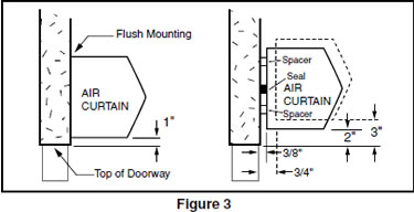
| B.
For optimum performance, the bottom of the air |
|
|
curtain (discharge nozzle) should be no more than
1” above the top of the door opening with the air
curtain(s) mounted flush to the wall. If the air
curtain must be mounted higher, it must be
spaced out from the wall 3/8” for every inch
the air curtain is above the door opening. See
Figure 3. For optimum protection, any void
between the air curtain and the wall should be
sealed along the full length of the air curtain. |
|
|
|
TABLE
1 - CHD10 Unit Weight |
TABLE
2 -
SHD07 Unit Weight |
C.
Do not block (obstruct) the air intake grill.
Insufficient airflow can cause the
unit to overheat. |
|
|
|
|
|
|
|
|
 |
| D.
Electric heated air curtain(s) shall: |
|
|
1.
Have a minimum clearance of at least 4”
between the sides and top of the air curtain
and any combustible material.
2. Have a minimum clearance of at least 6’
between the bottom of the air curtain and
the floor.
3. Be installed Indoors Only. |
|
|
|
|
|
E.
Proceed to either Section III - Wall Mounting
or Section IV - Suspended Mounting |
|
|
|
|
|
| III.
WALL MOUNTING |
|
 |
|
|
|
|
|
If
a wall mounting plate was ordered with the air curtain,
proceed to B. Wall Mounting – using the wall mounting
plate (sold separately), otherwise proceed: |
|
|
|
|
|
|
A.
WALL MOUNTING - without wall mounting
plate |
|
|
1.
Making sure that the air curtain is centered over |
|
|
|
the
opening, determine the exact mounting
location of the air curtain. |
|
|
|
|
|
|
|
|
NOTE:
A minimum of 4” is recommended above
the air curtain to provide clearance for installation
and removal of the cover housing. |
|
|
|
2.
Remove the screen by removing screws from |
|
|
|
|
the
top, bottom and front of the air curtain,
and slide the screen away from the blower
assembly. |
|
|
|
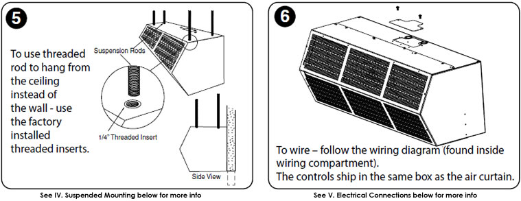
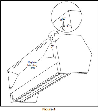
3.
The air curtain is equipped with four 1/4" key- |
|
|
|
|
hole
mounting slots on the back of each unit
for wall mounting. The slots are spaced 1"
from the ends, and 3/4" and 7" from the top.
See Figure 4. |
|
|
|
4.
Mark the wall according to the length of the air |
|
|
|
|
|
curtain.
The wall must provide sufficient support
for the air curtain. If the keyhole slots are not
located where suitable support is available, drill
new holes in the unit back plate where space is
available. |
|
|
|
|
5.
The mounting hardware (supplied by others) |
|
 |
|
|
must be capable of supporting a minimum of
three times the net weight of the air curtain. See
Weight Chart, Table 1 or Table 2. |
|
|
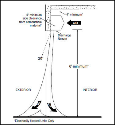
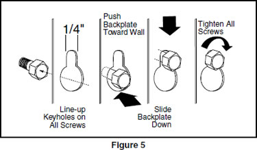
6.
Keyhole Mounting: Install the mounting |
|
|
|
hardware (supplied by others), allowing for
space to hang the air curtain by not fully
tightening. Without touching the blower wheels,
lift and slip the air curtain over the mounting
hardware by grasping the inlet rings of the
blower housing. Tighten the mounting hard-
ware. See Figure 5. |
|
|
|
|
|
|
7.
Drilled Mounting Holes: Lift the air curtain by |
|
|
|
|
grasping
the inlet rings on the blower housing,
without touching the blower wheels, and install
the mounting hardware (supplied by others)
through the drilled holes. |
|
|
|
8.
Reinstall the screen using hardware removed
in Step 2. |
|
|
|
9.
Proceed to Section V - Electrical Connections. |
|
|
|
|
|
|
|
B.
WALL MOUNTING – using the wall mounting
plate (sold separately) |
|
 |
|
|
|
|
| 1.
PREPARATION |
|
|
|
|
|
|
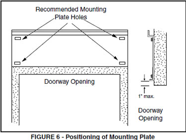
a.
Position and center the mounting plate over the |
|
|
|
door
opening. The mounting plate must be
positioned with the “Z” lip on top. Drill
mounting holes on the mounting plate.
See Figure 6. |
|
|
b.
Mark the wall in the center of each mounting |
|
|
|
plate
hole. The wall must provide sufficient
support for the air curtain. The mounting
hardware (supplied by others) must be
capable of supporting a minimum of three
times the net weight of the air curtain. See
Weight Chart, Table 1 or Table 2. If the
location of the marks on the wall do not
provide suitable support, mark and drill
additional holes. |
|
|
|
|
|
|
|
|
 |
|
c.
Drill the four holes as marked on the wall and |
|
|
|
attach
the mounting plate with anchors (if used)
and the four mounting screws (provided by
others). |
|
|
|
|
|
2.
ATTACHING THE AIR CURTAIN
TO THE MOUNTING PLATE |
|
|
|
|
|
|
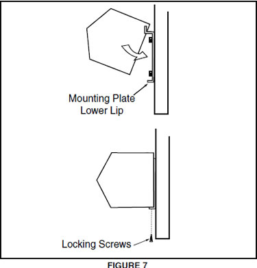
a.
Raise the air curtain over the door (air discharge |
|
|
|
nozzle
facing down) and on to the mounting
plate. First, tilt the unit upward matching the
rectangular openings to the “Z” lip on the
mounting plate. See Figure 7. |
|
|
b.
Lower the air curtain into place, allowing it to
rest on the lower lip of the mounting
plate. |
|
|
c.
After the air curtain is securely attached to the |
|
|
|
mounting
plate, re-install the two (2) locking
screws at the bottom corners. See Figure 7. |
|
|
|
|
|
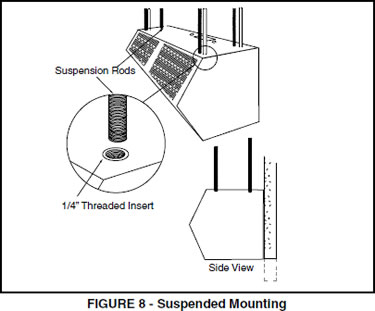
| IV.
SUSPENDED MOUNTING |
|
 |
|
|
|
| A.
For top mounting using suspension rods, four. |
|
|
(4)
factory installed 1/4” threaded inserts are
located in the top of the air curtain.
See Figure 8 |
|
| B.
Install 1/4” threaded rods, or other suitable |
|
|
hardware
at a location with sufficient support for
the air curtain. The mounting hardware (supplied
by others) must be capable of supporting a
minimum of three times the net weight of the air
curtain. See Weight Chart, Table 1 or Table 2. |
|
C.
Attach threaded rods, or other suitable hardware
to the top mounted threaded inserts. |
|
| D.
Proceed to Section V – Electrical Connections |
|
|
|
|
| V.
ELECTRICAL CONNECTIONS |
|
|
|
|
|
|
 |
All
electrical wiring and connections MUST be per-
formed by qualified personnel in accordance with
the latest edition of the National Electrical Code
ANSI/NFPA No. 70 or, in Canada, the Canadian
Electrical Code, Part 1-C.S.A. Standard C22.1
and local codes and regulations.
MAKE SURE THE CORRECT
VOLTAGE AS MARKED ON THE UNIT
IS USED. |
|
|
|
|
| A.
A separate line voltage supply with a suitable |
|
|
branch circuit protection device should be run
directly from the main electrical panel to the unit.
A disconnect switch for each branch circuit is a
required part of this installation. See the voltage
label on the unit for circuiting and total electrical
load. The wiring diagram is located in the wiring
compartment. |
|
|
|
|
|
|
|
VI.
FIELD CONNECTIONS |
|
|
|
|
|
|
A.
ELECTRICALLY HEATED MODELS |
| B.
All field wiring must be copper with a minimum |
|
|
|
The
heater circuit may be controlled by a remote
thermostat, manually through a unit mounted or
remote mounted three position - fan only/off/fan
with heat switch. Overheating protection is provided
by auto reset thermal cutouts built into the blower
assembly (see wiring diagram). Proceed to
Section VII - Operating Instructions. |
|
insulation
of 60°C within approved conduit. If any
of the wire supplied with the unit must be replaced,
it must be replaced with copper wiring with a
minimum insulation of 90°C. |
|
|
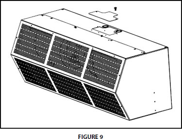
C.
Remove the wiring compartment cover on top
of the air curtain. See Figure 9. |
|
|
| D.
The top of the air curtain has knockouts on each |
|
|
|
|
|
|
side
of the wiring compartment. Remove the
required knockout and connect the power
supply to the air curtain. Connect all supply
and control circuit wires according to the
wiring diagram provided. |
|
|
|
|
|
|
|
|
|
NOTE:
For Electrically heated air curtains provided
with the optional remote thermostat, mount and wire
the thermostat according to thermostat instructions
and wiring diagram. |
|
|
|
|
|
|
|
|
|
For
Electrically heated air curtains proceed to
Section V - Field Connections, otherwise
proceed to Section VI - Airflow Adjustments |
|
|
|
|
|
|
|
|
|
|
|
| VII.
OPERATING INSTRUCTIONS |
|
 |
|
|
|
|
|
| A.
GENERAL OPERATION |
|
|
Air
curtain operation may be divided into four areas:
control package, fan activation, fan speed selection,
and heat activation. Depending on the type of
controls ordered one or more of the following
may be applicable. The air curtain must be properly
installed before it is used. |
|
|
1.
Control packages control the air curtain’s |
|
|
|
sequence
of operation. Unit modes/control
packages are built into the unit and may not
be changed in the field. Refer to your wiring
diagram for specifics about activation
connections and sequence of operation. |
|
|
|
|
|
|
|
|
a.
Basic Control Package – The unit is activated |
|
|
|
|
by
a door or selector switch. Either switch
may be line voltage or low voltage (24V). |
|
|
|
b.
Deluxe Control Package – The unit is |
|
|
|
|
activated
by a door or selector switch, but
has a factory installed time delay allowing
the unit to keep running for a period of
time after the door closes. |
|
|
|
|
|
|
|
|
|
|
|
|
B.
AIR STREAM ADJUSTMENT |
|
|
|
|
|
|
|
|
|
|
|
|
1.
With the air curtain operating and the door in. |
|
|
|
|
|
|
its
full open position, check to see that nothing is
obstructing the airflow at the discharge nozzle
vanes. |
|
|
c.
Comfort Plus Control Package – Available |
|
|
|
|
|
|
only
on heated units, the unit is activated by
a door or selector switch AND a thermostat
to provide supplemental heating.
NOTE: Not available with 575V motors. |
|
|
|
|
|
|
|
|
|
|
|
|
|
|
|
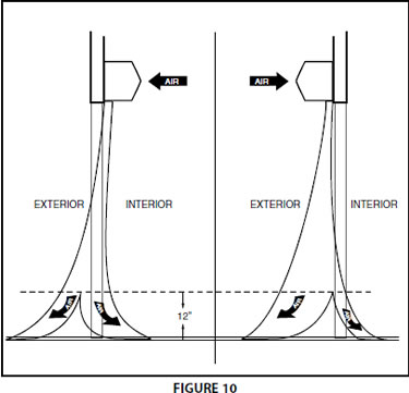
2.
Find the air stream split location. Hold a hand- |
|
|
|
|
|
|
kerchief
by its corners, approximately 12” above
the floor. Gently move the handkerchief back
and forth in the doorway. Make sure the air is
being directed to both the inside and the outside.
See Figure 10. The split location is indicated
where the handkerchief is vertical with minimal
or no fluttering. |
|
|
|
|
|
|
|
|
2.
Unheated air curtains will have the fans |
|
|
|
|
|
activated
by a door or selector switch or
sensor. The unit may be single speed and
require no fan speed selector (On/Off), or may
have three fan speeds which require either a
unit or remote mounted switch (Off, High,
Med, Low). |
|
|
|
|
|
|
|
|
|
|
|
|
|
3.
The split location should be approximately 3” |
|
|
|
|
|
outside
the doorway. If necessary adjust the
discharge nozzle vanes by de-energizing the unit,
loosening the nozzle vane locking screws and
adjusting vanes. |
|
|
|
|
|
|
|
|
3.
Heated air curtains will have fans activated by |
|
|
|
|
|
a door or selector switch or sensor, but may
also be activated by the thermostat in Comfort
Plus Mode. The unit has three fan speeds
which can be set by either a unit or remote
mounted switch (Low, Med, High, Off, Low
heat, Med Heat, High Heat). |
|
|
|
|
|
|
|
|
|
|
|
|
|
|
|
|
|
|
4.
Heat activation is controlled by either a unit or |
|
|
|
|
|
|
remote mounted thermostat, and a unit or remote
mounted switch. |
|
|
|
|
|
|
|
|
|
| VIII.
MAINTENANCE & CLEANING |
|
 |
|
|
|
|
CAUTION:
ELECTRIC SHOCK HAZARD
Disconnect power whenever servicing unit.
More than one disconnect may be required
to de-energize unit. |
|
|
|
|
|
Keep
your air curtain operating at peak efficiency by
cleaning the blower wheels, motor(s) and intake grill.
Buildup of dust on the blower wheels can cause
vibration, noise and excessive wear on the motor
bearings. The frequency of cleaning will depend
on the environment where the unit is operating. |
|
|
|
|
|
Dirty,
dusty or greasy environments could require a
cleaning schedule of once every two months. If the
environment is not that dirty, the unit(s) should be
scheduled for cleaning a minimum of once every
(6) months. |
|
|
|
|
|
A.
PERFORMING PREVENTIVE
MAINTENANCE |
|
|
|
|
1.
Disconnect and lockout power to the unit. |
|
IX.
SERVICE |
|
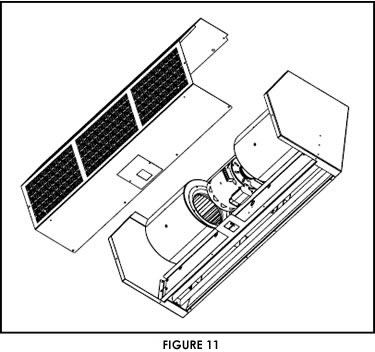
2.
Remove the intake screen by removing the |
|
|
|
|
Any
service performed on the air curtain MUST be
done by qualified personnel. |
|
|
machine
screws located around the bottom,
front and top of the screen See Figure 11. |
|
|
|
|
Our
air curtains require very little servicing. All parts
are easily accessible for periodic inspection and
maintenance. Units should be cleaned at least twice
a year. Your particular application (the amount of dirt
and dust in the air) and location of the unit(s) will
determine how often your unit(s) will need to be
cleaned and serviced. All motors have permanently
lubricated, sealed, sleeve bearings and require no
maintenance |
|
3.
Vacuum and scrape (if necessary) to remove |
|
|
|
the
build-up of dirt and debris. The motor(s)
are permanently lubricated and require no
additional lubrication. Re-install the cover
and intake grill. |
|
|
4.
Switch the power on after cleaning. |
|
|
|
|
|
CAUTION:
STAND CLEAR OF THE UNIT OR
WEAR SAFETY GOGGLES AS LOOSE DEBRIS
MAY BE PRESENT AND MAY EXIT THE
NOZZLE. |
|
|
|
|
High Performance
Unheated Air Curtains, High Performance Air Curtains, Commercial
Air Curtains, Commercial Air Door,
Unheated Air Curtains, and Insect Barrier from your source
for material handling equipment.
|
Back to Product
Page
|