Back to Product Page
|
ENERGY-EFFICIENT
INSECT
ELECTROCUTORS
|
 |
|
|
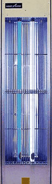
VERTICAL
WALL MOUNT SERIES 9 & 11
|
|
|
|
|
|
|
|
|
|
Most
flying insects are phototropic (attracted to light).
Specifically, houseflies and other nuisance flying
insects are highly attracted to light energy in the near
ultraviolet (black light) spectrum. |
|
 |
|
|
|
|
|
|
|
|
|
|
|
|
|
 |
|
|
|
|
|
|
|
|
|
|
|
|
Wavelengths
between 330 and 360 Nanometers
provide the best attraction. These wavelengths are
neither visible nor harmful to human... but are
extremely visible and attractive to flying insects. |
|
|
|
|
|
|
|
|
|
|
|
|
|
|
|
|
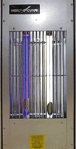
The
Insect-O-Cutor® method uses an ultrahigh
intensity (UHI™) black light source to attract flying
insects to an electrified grid where they are killed
upon contact. The dead insects are then collected
in a drawer or tray for periodic inspection and disposal. |
|
|
|
|
|
|
|
|
|
|
|
|
|
|
|
|
Designed
for high-traffic areas, typical Vertical
Wall Mounted Model installations include
personnel doors, loading dock areas, along
corridors, at firewall breaks, and at virtually all
exterior access points. |
|
|
|
|
|
|
|
|
|
|
|
|
|
|
|
|
|
|
|
|
|
Series
11
|
|
|
|
Series
9
|
|
|
|
|
|
|
|
|
|
|
|
|
|
|
|
TECHNICAL DATA AND ELECTRICAL SPECIFICATIONS
|
ENERGY
EFFICIENT
(EE) MODELS |
|
|
|
|
|
|
|
|
|
|
|
120
VOLT/60 HZ MODELS
|
|
|
|
220
VOLT/50 HZ MODELS
|
|
are
designed to comply with
various energy compliance acts
and energy conservation
programs. Electronic-ballasted
models reduce overall electrical
consumption, while increasing
light output by 8% to 15% per
lamp due to increased operational
efficiency. Less energy consumed…
more insect attraction light emitted. |
|
| PRIMARY:
120 VOLTS, 60 HERTZ |
PRIMARY:
220 VOLTS, 50 HERTZ |
|
| SECONDARY:
4500 VOLTS |
SECONDARY:
5000 VOLTS |
|
|
NOTE: UNIT MUST BE GROUNDED.
|
|
|
|
|
|
|
|
|
|
|
TRANSFORMER
(WITH INTERNAL
CAPACITANCE): T740C |
|
|
|
|
|
|
|
|
|
|
|
|
|
|
|
|
TRANSFORMER
(WITH INTERNAL
CAPACITANCE): T1040C-2 |
|
mA
OUTPUT: 9.8
AMP. INPUT -
EE MODELS: 1.4-1.5 |
|
|
|
|
|
|
|
mA
OUTPUT............... 10.0
AMP. INPUT .............. 0.40 |
|
|
|
|
|
|
|
|
UNIVERSAL
VOLTAGE BALLAST —
(ONE PER UNIT): ..............BPU |
|
|
|
HIGH
PERFORMANCE BALLAST —
ONE OF EACH LAMP: |
|
|
|
|
|
|
|
|
| PRIMARY:
......................BP18 (SERIES 9) |
|
|
|
|
|
|
|
| AUXILIARY:
: ................N/A (SERIES 9) |
|
|
|
|
|
|
|
|
STANDARD
FEATURES: |
|
| PRIMARY:
......................BP48 (SERIES11) |
|
|
| AUXILIARY:
: ............... BA48 (SERIES 11) |
|
|
|
Rear
keyhole slots for wall mounting. Safety guard; safety switch
interrupts electrical current when servicing unit; internal
metal insect
collection drawer; spring-loaded and fixed lampholder sets for
simple
lamp installation; reflector panel increases black light emission…
three-
wire grounded cord and plug. 120Volt Models are safety-tested
and
certified by Intertek Testing Services, N.A. Inc. (ETLcm). |
|
|
|
|
ENERGY
EFFICIENT BALLASTS —
ONE PER UNIT: BPE18 (SERIES 9) |
|
|
ENERGY
EFFICIENT BALLASTS —
ONE PER UNIT: BPE24/48-2 (SERIES 11) |
|
|
|
|
|
PACKED
CARTON: 6.6 CUBIC FEET /
0.18 CUBIC METERS (SERIES 11) |
|
|
PACKED
CARTON:3.4 CUBIC FEET /
0.10 CUBIC METERS (SERIES 9) |
|
|
|
|
|
|
|
|
|
|
|
|
|
|
|
|
|
|
|
|
|
|
|
|
|
 |
|
Order
Online, by Phone, or by E-Mail |
|
|
|
~
Add items to your online shopping cart ~
Click the Model No. of the item
you wish to purchase.
|
|
|
|
|
PRICING
FOR SERIES 9
|
|
Model No. |
Black Light
Attraction Lamps |
Unit Dimensions
W x H x D |
Shipping
Weight (lbs.) |
Metal Materials |
Price |
| 994EDG |
18 and 18B |
13.25" x 27" x 5.25" |
25 |
Sand Beige Textured |
$1,424
|
| 994EDGA |
18 and 18B |
13.25" x 27" x 5.25" |
25 |
Aluminized Steel |
$1,424
|
| 994EDGS |
18 and 18B |
13.25" x 27" x 5.25" |
28 |
Stainless Steel |
$1,811
|
|
|
|
|
|
|
PRICING
FOR SERIES 11
|
|
Model No. |
Black Light
Attraction Lamps |
Unit Dimensions
W x H x D |
Shipping
Weight (lbs.) |
Metal Materials |
Price |
| 1199EDG |
48 and 48B |
16.25" x 60" x 7.25" |
66 |
Sand Beige Textured |
$2,374
|
| 1199EDGA |
48 and 48B |
16.25" x 60" x 7.25" |
66 |
Aluminized Steel |
$2,374
|
| 1199EDGS |
48 and 48B |
16.25" x 60" x 7.25" |
73 |
Stainless Steel |
$3,124
|
|
|
|
|
|
|
EXPLANATION
OF INSECT-O-CUTOR® MODEL SUFFIXES:
|
|
|
|
|
| E
= ENERGY-EFFICIENT |
D
= INTERNAL COLLECTION DRAWER |
G
= SAFETY GUARD |
A
= ALUMINIZED STEEL
CONSTRUCTION |
S
= STAINLESS STEEL CONSTRUCTION |
T
= EXTERNAL COLLECTION TRAY |
| R
= RECESSED MODEL |
|
|
|
|
Frequently
Asked Questions
|
|
|
|
|
|
|
|
 |
What
types of insects are attracted to Insect-O-Cutors? |
|
|
|
|
|
|
|
|
|
|
|
|
|
|
|
There
are very few types of flying insects which are not attracted
by near-ultraviolet light.
Thus, there are very few flying insects which are not attracted
to Insect-O-Cutors. |
|
|
|
|
|
|
|
|
|
How
large an area will an Insect-O-Cutor cover? |
|
|
|
|
|
|
|
|
|
|
|
|
|
Coverage
by a particular model depends upon many factors. Among these
factors are: types
of insects; competing light and other attractions; air temperature
and movement. A general rule
of thumb is to locate Insect-O-Cutors so that insects need not
be attracted more than 35 to 40 feet. |
|
|
|
|
|
|
|
|
Do
Insect-O-Cutors meet O.S.H.A. requirements? |
|
|
|
|
|
|
|
|
|
|
|
Yes,
when installed in accordance to Insect-O-Cutor recommendations
and specifications, and
in compliance with governing authorities, bureaus and agencies.
(In the U.S., refer to the current
edition of the National Electrical Code (NEC). |
|
|
|
|
|
|
|
|
What
is the life of an Insect-O-Cutor unit? |
|
|
|
|
|
|
|
|
|
|
|
Fifteen,
twenty or more years... with proper maintenance. |
|
|
|
|
|
|
|
|
Is
black light dangerous? |
|
|
|
|
|
|
|
|
|
|
|
The
near-ultraviolet light lamps used in Insect-O-Cutors peak at
357 Nanometers which is a
wavelength that is normally harmless to humans. This is a question
often asked because a number
of people have heard of ultraviolet "germicidal" lamps
used in air sterilization, purification and
disinfection fixtures. |
|
|
|
|
|
|
|
|
During
what hours should Insect-O-Cutors operate? |
|
|
|
|
|
|
|
|
|
|
|
Insect-O-Cutors
should be allowed to operate twenty-four hours a day, seven
days a week,
during the flying insect season. |
|
|
|
|
|
|
|
|
How
long will the black light lamps last in an Insect-O-Cutor? |
|
|
|
|
|
|
|
|
|
|
|
Although
the lamps will continue to light for several years in many instances,
emission levels of near-
ultraviolet light will drop below acceptable levels after approximately
seven months of use. It is
strongly recommended by Insect-O-Cutor as well as the lamp manufacturers
that lamp replacement
be made on an annual basis. |
|
|
|
|
|
|
|
|
Is
there much maintenance required? |
|
|
|
|
|
|
|
|
|
|
|
Other
than lamp replacement (which should be performed at least annually),
Insect-O-Cutors
should be cleaned periodically. This constitutes brushing debris
from the grid kill area, emptying
the collection drawers, and wiping exterior surfaces with a
dampened cloth. |
|
|
ABOUT
BLACK LIGHT
|
|
|
|
|
|
|
|
| LIGHT
AND THE SPECTRUM |
|
HEALTH
AND SAFETY ISSUES |
|
|
|
|
|
|
|
Insect
attraction lamps, like all lamps, emit energy in
the form of light. This energy is measured in wavelengths.
By determining wavelength measurements,
classification of different light types within the full light
spectrum is possible. |
|
The
primary health concerns most often associated
with ultraviolet light relate to skin irritation (erythema)
and eye irritation (conjunctivitis). Such irritations might
occur when an individual is exposed to light energy
emitted under 3200 nanometers. |
|
|
|
|
|
|
|
Some
types of light energy classifications include:
InfraRed, Visible (sunlight), and Ultraviolet [UV]. |
|
Lamps
emitting energy below this wavelength are
within the Middle UV and Far UV ranges — and are
commonly referred to as “tanning lamps” and
“germicidal” lamps, respectively. |
|
|
|
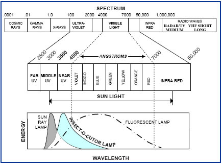
Ultraviolet
energy is measured and defined by light
within a band between 4000 and 1000 Angstroms (400
and 100 nanometers). Within this band of the light
spectrum, ultraviolet energy is further classified into
four sections: Near UV [UVA], Middle UV [UVB], Far
UV [UVC] and Vacuum UV. |
|
|
|
|
|
|
|
Insect-O-Cutor®’s
Gold Label™ insect attraction lamps
emit light energy at 365 nanometers (UVA). |
|
|
|
|
|
|
While
UVA energy is well above the harmful UVB
range of energy (320 nanometers), certain thresholds
of exposure to UV light sources have been established
by OSHA to ensure personnel safety as related below: |
|
|
|
Insect-O-Cutor®
insect attraction lamps emit light energy
within the Ultraviolet band of the light spectrum, specifically
light in the Near UV range. |
|
|
|
|
|
|
|
|
|
|
|
|
|
This
range of energy
is measured by wavelengths
between 400
and 350 nanometers. |
|
|
|
|
|
150,000
hours — |
 |
|
|
of
continuous exposure
at a distance of twenty
feet (20') or 6.1 meters
from a light source; |
|
|
|
Regarding
flying insect
attraction, UVA
energy is most effective
at 365 nanometers.
This particular wave-
length is commonly
referred to as Black
Light. |
|
|
|
1,500
hours — |
|
of
continuous exposure
at a distance of six
feet (6') or 1.83
meters from a light
source; |
|
|
|
Forty
(40) hours — |
|
of
continuous exposure
at a distance of one
foot (.3048 meter)
from a light source. |
|
|
BLACK
LIGHT (BL)
AND BLACK
LIGHT BLUE
(BLB) |
|
|
|
|
|
|
|
|
|
|
|
|
|
|
The
BL lamp produces most of its energy in the Near
UV range. However, a portion of the energy is outside the
UV range as the light spectrum enters the Visible Light
range. Note in the graph that visible light ranges from
Violet to Red. The lesser portion of the energy emitted
by the BL lamp is in the Blue Visible range. [This is what
we humans see as visible light.] |
|
|
|
|
|
SOURCES:
General Electric Lighting Company; Philips
Lighting; Sylvania GTE Products;
New England Journal of Medicine; Occupational
Health and Safety Administration (OSHA). |
|
|
|
|
|
|
|
|
|
|
|
The
BLB lamp produces its energy in the same
wavelength range that the BL lamp does. However,
the BLB lamp is constructed of special filtering
glass which reduces the passage of energy in the
visible light range between 4000 and 4600 Angstroms
(400 to 460 nanometers). |
|
|
|
|
|
|
|
|
|
|
Because
of this filtering of blue visible light, the lamp
does not have the light blue color that the BL lamp
does but instead appears as a blue/black color. |
|
|
|
INSTRUCTION
AND
MAINTENANCE MANUAL
|
|
|
|
| SAFETY
PRECAUTIONS — READ THIS SECTION FIRST |
|
|
|
| CAUTION |
HIGH
VOLTAGE, DISCONNECT BEFORE SERVICING. |
|
|
|
| CAUTION |
TO
REDUCE THE RISK OF FIRE OR ELECTRIC SHOCK, USE INDOORS ONLY
—
SEE INSTRUCTIONS. This product is intended for use indoors
only. To avoid risk
of fire or electric shock, do not use where it may be exposed
to direct water or direct sunlight
including roofed but open porches. |
|
|
|
|
| CAUTION |
NEVER
INSTALL INSECT-O-CUTOR® (IOC®) EQUIPMENT NEAR EXPLOSION
HAZARDOUS AREAS. (Areas defined as Class I, II or III —
See the Code of Federal Regulations). |
|
|
|
|
| CAUTION |
TO
PROVIDE CONTINUED PROTECTION AGAINST THE RISK OF ELECTRIC
SHOCK CONNECT TO PROPERLY GROUNDED OUTLETS ONLY. For your
safety,
consult a qualified electrician or serviceman if the grounding
instructions are not completely
understood, or if doubt exists as to whether the unit has been
properly grounded. |
|
|
|
|
| CAUTION |
TO
REDUCE THE RISK OF FIRE, REMOVE THE DEAD INSECTS
FREQUENTLY. See “Preventative Maintenance Program”
below. |
|
|
|
|
| CAUTION |
Use
extension cord marked SJW-A, SJEW-A, or SJTW-A only. Use only
three-wire extension
cords which have 3-prong plugs and 3-pole receptacles which
accept the attachment plug. Replace
or repair damaged cords. |
|
|
|
|
| CAUTION |
The
electrical rating of the extension cord must be as great as
the electrical rating of the product.
DO NOT ABUSE THE CORD. Never carry an Insect-O-Cutor®
by its cord or yank the
cord to disconnect it from the receptacle. Keep the cord from
heat, oil, and sharp edges. Any frayed
or worn cord should be repaired or replaced at once. |
|
|
|
|
| Contains
Mercury, Dispose According to Local, State or Federal Laws |
|
|
|
|
DISCONNECT
THE PRODUCT FROM THE POWER SUPPLY when not
in use; before servicing; when changing black light lamps;
cleaning; and the like.
Do not insert foreign objects into an IOC® product.
|
|
|
|
|
|
|
|
|
|
|
|
|
GENERAL
LOCATION RECOMMENDATIONS
|
|
|
|
|
|
|
|
|
|
|
|
|
PRIOR
TO INSTALLING THE UNIT(S), PLEASE READ “ASSEMBLY AND
INSTALLATION
INSTRUCTIONS”: BELOW
|
|
|
|
|
|
|
|
|
|
|
|
An
Insect-O-Cutor® (IOC®) system may consist
of a single unit protecting a small area or many units
protecting an entire facility. A single unit can be
properly located/positioned by following our
general positioning recommendations. A multiunit
system may require the assistance of an
IOC® Systems Design Engineer or an authorized
representative. |
2.
HANGING UNITS NEAR OUTSIDE ENTRY POINTS |
|
|
|
|
|
|
|
 |
FOR
DAY-SHIFT OPERATIONS
|
|
|
Locate
Unit
Parallel to the Door
|
|
|
Position
units broadside to the
area to be protected, or to the
exterior doors so that black light
attraction will face these insect
entry points. |
|
|
|
|
|
|
|
|
|
|
|
If
an IOC® survey proposal has been provided,
follow the instructions for exact positioning of the
units. If a survey proposal with location instructions
was not provided, adhere to the following
general guidelines. |
|
|
|
|
|
|
|
|
|
 |
FOR
MULTI-SHIFT
OPERATIONS
|
|
|
|
|
|
Locate
Unit
Perpendicular to the Door
|
|
|
|
|
|
|
| 1.
LOCATION — ALL MODELS |
|
|
If
the exterior doors will be open
for prolonged periods during
hours of darkness, units should be
positioned at a 90° angle to the
doors. |
|
|
|
|
|
|
|
a)
Choose a location that will provide interception
of flying insects between the point of entry
into the
building and critical contamination areas
(use at
least one unit for each entry point). |
|
|
|
|
|
|
|
|
|
|
|
|
|
|
|
|
|
|
|
|
|
|
|
|
|
|
b)
Place the unit a minimum of 10 to 15 feet (3-5
meters) from any exterior opening to minimize
the possibility of emitting insect attraction
light
out of any exterior opening. |
|
|
|
|
|
|
| 3.
GENERAL INFORMATION |
|
|
|
|
|
|
|
DO
NOT PUT THE IOC® UNIT WHERE YOU
“DO NOT WANT THE INSECTS”. For instance, do not
put an IOC® unit on the far side of a production line or
other point of possible contamination, in relation to
the point of entry. |
|
|
|
|
|
|
c)
Install the unit a minimum of 10 feet (3 meters)
from highly reflective surfaces. |
|
|
|
|
|
|
d)
Avoid setting unit near air currents from fans,
ducts, heat vents or other air movers. |
|
|
|
|
|
|
|
Locate
the unit between the product and the insect
entry point to intercept insects or lure insects from
critical areas. |
|
|
|
|
|
|
e)
Avoid placing equipment near high intensity
artificial light that might compete with
the unit’s black light attraction lamps. |
|
|
|
 |
|
|
|
|
f)
REMEMBER: The process of insect
electrocution creates an electrical arc.
Contact Insect-O-Cutor® or one of its
representatives for assistance regarding
location of units in questionable areas. |
|
|
|
|
|
CAUTION:
|
|
|
NEVER
LOCATE A UNIT IN AN
EXPLOSION HAZARDOUS AREA.
|
|
| |
Examples:
Near areas where bulk flour,
sugar, grains, and other fine particles
(including dust) are present and/or airborne
in proximity to flammable gases,
oils, chemicals, and other igneous liquids;
near battery chargers; in surgical suites
and other medical areas where explosive
or flammable/combustible anaesthetic
agents are used. |
|
|
|
|
|
|
|
|
|
|
For
maximum flying insect elimination, an IOC® System should
consist of Three Phases. Phase I units intercept insects at
immediate points of entry. |
|
|
|
|
|
|
|
|
|
|
Phase
II units, located between entry points and critical interior
areas, intercept insects at such places as firewall breaks and
along corridors. |
|
|
|
|
|
|
|
|
|
|
|
|
|
|
|
|
|
|
Phase
III units provide the final line of interception. In some
situations, units may be located within the critical area. [Critical
areas are those in which the least amount of flying insects
should
be found, if any.] |
|
|
|
|
|
|
|
|
|
ASSEMBLY
AND INSTALLATION
|
|
|
|
|
|
|
|
|
HANGING/OVERHEAD
SUSPENDED MODELS
|
|
WALL
MOUNTED MODELS
|
|
|
|
|
|
|
|
|
SERIES
312, 372, 389, 399, 492,
494, 589, 599, 2489, 2499, 3692,
3694, 4889, 4899, AND 894
|
|
|
|
|
|
|
|
|
SERIES
372, 812, 994, 6192, 6199, 1192, 1199,
7194, 1890, 1894, 2489, 2499, 2591, 2594,
2599, 3692, 3694, 4889, 4899, AND 894
|
|
|
|
|
|
|
|
|
|
|
|
| A.
Remove unit from carton; discard packing materials. |
|
A.
Remove unit from carton; discard packing materials. |
|
|
|
|
|
|
|
A.1
Series 372, 894, 2489, 2499, 3692, 3694, 4889,
and 4899 |
|
B.1
ASSEMBLY — Series 812, 994, 6192, 6199,
1192, 1199, 7194, 1890,
1894, 2591, 2594,
and 2599 |
|
These
models may be either overhead suspended or
wall mounted. To install as a hanging unit, remove
the optional reflective backplate accessory. The
backplate is required when wall mounting the unit . |
|
|
|
Units
are shipped completely assembled. An insect
collection drawer is packed inside each unit. |
|
|
|
|
|
|
|
B.2
ASSEMBLY — Series 372, 894, 2489, 2499,
3692, 3694, 4889, and 4899 |
|
|
|
|
B.
Screw the provided eyebolts through the threaded
holes located on the body of the unit
as shown
below: |
|
|
|
|
|
|
|
|
These
series models may be wall mounted or
overhead suspended. For wall mount installations,
an optional backplate is provided with each unit.
Do not remove this backplate; it is an essential part
when the unit is wall mounted. An insect collection
drawer is packed inside each unit. |
|
|
|
|
|
|
 |
|
|
|
|
|
|
|
|
C.1
INSTALLATION — Series 812, 994, 6192,
6199, 1192, 1199, and 7194 |
|
|
|
|
|
|
Recommended
mounting is to secure the unit to a
wall or pillar. Generally, the bottom of the unit should
be no lower than 18 inches (47 centimeters) from the
floor, and the center of the unit should not exceed
five [5] feet (1.5 meters) above the floor. The unit
should be attached to a vertical surface by inserting
lag bolts or screws through the keyshaped mounting
holes in the rear of the unit after properly inserting
and securing the lag bolts or screws into the wall/pillar. |
|
|
|
|
|
Make
certain the eyebolts are threaded properly into
the locknuts to ensure a secure hold. |
|
|
|
|
|
|
|
|
|
|
|
|
|
|
C.
Attach the required length of chain or cable to each
eyebolt (using an “S” hook).
Caution: Use a
minimum 200 Lb. (90 to 100 Kg) test
“S” hook, chain
or cable. |
|
|
|
|
C.2
INSTALLATION — Series 372, 2489, 2499,
3692, 3694, 4889, 4899,
894, 1890, 1894, 2591,
2594 and 2599 |
|
|
|
|
|
These
series models may be used as free standing
units on or under counters, tables, benches or
shelves that adequately support the unit’s weight. |
|
|
|
|
|
|
D.
Attach the “S” hooks and chain or cable to the
ceiling,
roof truss, beam or bracket which has adequate
strength to support the weight. When the chain (or
cable) has been attached, test it for supportability of
the product weight before hanging the unit. |
|
|
|
|
|
|
|
Note:
For security purposes, it is recommended
that the unit be permanently affixed to a wall, pillar,
or other vertical surface. |
|
|
|
|
|
|
|
|
PORTABLE
SERIES 372, 2489, 2499,
1890, 1894, 2591, 2594 AND 2599
|
|
|
|
|
|
|
|
|
|
The
unit should be attached to a vertical surface by
inserting lag bolts or screws through the keyshaped
mounting holes in the rear of the unit after properly
inserting and securing the lag bolts or screws into
the wall. |
|
|
|
|
|
|
|
These
models, equipped with a carrying handle and
protective footpegs, may be used to provide spot
protection in temporary areas or as a monitor in
specific problem areas. It is not necessary to remove
the carrying handle should you elect to permanently
install the unit. Simply install the unit according to
the appropriate instructions. |
|
|
|
|
|
|
|
|
|
Designated
as “low headroom”, these horizontally
configured models are ideal for use in areas where
ceiling heights are limited or where vertical wall
space is at a premium. Units may be installed
securely over doorways. |
|
|
|
|
|
|
|
|
|
|
|
ALL
MODELS: HANGING/OVERHEAD SUSPENDED AND WALL MOUNTED
|
|
|
|
|
|
CONNECTING
UNITS TO POWER SOURCE:
|
|
|
|
|
| AFTER
INSTALLING THE UNITS — |
|
|
|
|
|
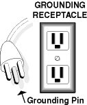
PLUG
INTO A STANDARD 110/120V, 60 HZ POWER SUPPLY. UNITS MUST BE
GROUNDED.
|
|
|
|
|
This
product is equipped with an NRTL approved
three-conductor cord and three-prong grounding
type plug to fit the proper grounding type receptacle. |
|
If
necessary, use extension cords marked SJW-A,
SJEW-A, or SJTW-A only. Use only 3-wire extension
cords which have 3-prong grounding-type plugs and
3-pole receptacles which accept the Insect-O-
Cutor® plug. Replace or repair damaged cords. |
|
|
|
To
reduce the risk of an electric shock, the plug must
be plugged into an appropriate outlet that is properly
installed and grounded. |
|
|
|
|
The
electrical rating of the extension cord must be as
great as the electrical rating of the product. Refer to
the unit’s electrical rating label. |
|
 |
|
| FOR
YOUR SAFETY: |
|
|
|
Consult
a qualified electrician
or serviceman if the grounding instructions are not completely
understood … or if doubt exists
as to whether the unit has been
properly grounded. |
|
|
|
|
DO
NOT ABUSE CORD. Never carry an IOC®
product by the cord or yank the cord to disconnect it
from a receptacle. Keep the cord away from heat, oil,
and sharp edges. Any frayed or worn cord should be
repaired or replaced at once. |
|
|
|
|
|
|
|
Disconnect
the product from the power supply when
not in use, before servicing, when changing lamps,
cleaning, and the like. |
|
|
|
|
|
|
|
INSECT-O-CUTOR®
DESIGN FEATURES
|
|
|
|
| SAFETY
INTERRUPT SWITCH |
|
SAFETY
GUARD FLANGE
|
|
|
|
Partial
or complete removal of the guard will activate
the safety interrupt switch; electrical current to the
unit will be automatically shut off. Electrical current
will remain off until the guard has been replaced in
its original seated position on the unit’s bodyframe. |
|
Series
3692, 3694, 4889, 4899, and 894 are equipped
with a metal safety guard flange to act as a retainer
which allows authorized personnel to prop the guard
open for maintenance/service. |
|
|
|
BLACK
LIGHT LAMPS
|
|
|
|
|
|
|
PROTECTIVE
GUARDS
|
|
|
|
IOC®
units are shipped with the lamps in place. Certain
models are shipped with cardboard lamp supports to
prevent breakage in transit; remove and discard these
lamp supports prior to use. |
|
|
The
front guard on hanging/overhead suspended
models and the entire guard panel of wall mount
models must fit snugly to the unit’s bodyframe in order
for the unit to function. See “Safety Interrupt Switch”
above. |
|
|
|
|
Note:
Tape securing lamp ends to lampholders must
be removed and discarded prior to use. |
|
|
|
|
|
Firm
pressure should be applied to the guard when
replacing it into an operating position so that the
interlocking fasteners join. |
|
|
|
COLLECTION
DRAWERS
|
|
|
|
Insect
collection drawers are packed inside some units.
These drawers should be periodically removed to
inspect and discard collected insect carcasses. |
|
|
|
|
|
|
|
|
TROUBLE
SHOOTING TIPS
|
|
|
|
|
|
| 1.
LAMP END DISCOLORATION |
|
3.
THE GRID ARCS CONSTANTLY |
|
|
|
|
|
a.
Discoloration of the lamp ends is normal in most cases
— and will not reduce lamp efficiency. |
|
|
|
|
a.
Inspect the electrical grid (please follow the |
|
|
procedure
described in Problem 2). If arc’ing
occurs at only one spot, shut off the electrical
current and clean the grid, making sure
the wires are not bent. |
|
|
|
|
| 2.
ONE OR BOTH LAMPS FAIL TO LIGHT |
|
|
|
|
|
|
| a.
Verify lamp pins are properly seated in the |
|
|
|
lampholders.
Using a non-electrical conducting
safety tool (insulated screwdriver, etc.), arc the grid
by holding the tool briefly between two grid wires.
This usually will start/light the lamps. If not, proceed
with the steps below. |
|
|
|
|
|
|
|
|
b.
Verify the line voltage. Line voltage above |
|
|
|
120
Volts may cause arc’ing, particularly in the
presence of high humidity/moisture. |
|
|
|
Note:
100-Ohm Resistors with installation
instructions are available from Insect-O-Cutor®.
Resistors may resolve spontaneous arc’ing
associated with environmental factors such as
humidity, etc. |
|
|
|
|
| b.
Check for loose wiring after disconnecting or |
|
|
|
shutting
off the electrical current to the unit. |
|
|
|
|
|
|
| c.
Replace inoperable lamp(s) with new IOC® insect |
|
|
|
attraction
lamps. First review Step (d) below. |
|
|
|
|
|
|
|
|
4.
THE LAMPS LIGHT — BUT THE GRID
DOES NOT ARC |
|
|
|
| d.
When replacing a black light insect attraction lamp |
|
|
that is not lit, follow the steps below to help prevent
burning out a new lamp unnecessarily: |
|
|
|
|
|
|
|
a.
Turn off the electrical current to the unit. |
|
|
|
|
|
|
b.
Inspect the grid carefully. Remove any foreign |
|
|
|
|
1.
Ensure that the electrical current to the unit has
been turned off. |
|
|
|
|
material
(gum, paper clips, steel wool, etc.)
adhering to the grid which can create a short
circuit between two grid wires. |
|
2.
Remove the unlit lamp. |
|
|
|
3.
Remove the other lamp in the unit that is lit. |
|
|
|
|
|
|
|
|
c.
Two or more grid wires may be touching each |
|
4.
Place the unlit lamp in the position from which
you have just removed the lit lamp. |
|
|
|
|
other
and causing a short circuit in the grid
(due to a special built-in safety shunt which
turns off the electrical current). In this instance
(unit already should have been turned off ),
separate and bend the grid wires apart with an
insulated tool . |
|
5.
Turn the unit on by closing the safety guard to
deactivate the interrupt switch and restore
electrical
current. |
|
|
|
|
|
|
If
the unlit lamp now lights, this indicates that the
ballasts in the first lamp position have possibly failed. |
|
|
|
|
|
|
d.
Inspect the high-voltage lead-in wires and |
|
|
|
If
the unlit lamp does not light, insert an ordinary white
fluorescent lamp (of the same wattage) in the position
originally occupied by the unlit lamp. If this lamp glows
red briefly and then goes out… or if this lamp does not
light at all, the ballasts which power this lamp position
are defective. |
|
|
|
insulators.
Make sure the wires are securely
attached to the grid. Check the insulators for
evidence of shorting. |
|
|
|
|
e.
Turn on the unit to ascertain whether the |
|
|
problem
has been corrected. |
|
|
|
|
|
| e.
If you have confirmed that one or more |
|
|
|
|
f.
If, after completing Steps (a) through (e) above, |
|
ballasts
are defective, it will be necessary to replace
them. Refer to the IOC® Replacement Parts List
(separate sheet) for the correct re-order information. |
|
|
|
|
the
grid still does not arc, it will be necessary to
replace the transformer. Refer to the IOC®
Replacement Parts List (separate sheet) for the
correct re-order information. |
|
|
|
|
|
|
|
|
|
|
DO
NOT INSERT FOREIGN OBJECTS INTO AN IOC® PRODUCT.
|
CAUTION:
Insect-O-Cutor® models are intended for use indoors only.
To avoid risk of fire or
electric shock, do not use where they may be exposed to direct
water or to direct sunlight
including roofed but open porches. Never install units near
explosion hazardous areas.
Refer to “Location Recommendations” above. |
|
|
|
|
|
|
5.
THE LAMPS DO NOT LIGHT — AND
THE GRID DOES NOT ARC.
|
|
6.
THE LAMPS OPERATE… THE GRID
FUNCTIONS — BUT INSECTS ARE
NOT ATTRACTED TO THE UNIT AS
WELL AS EXPECTED.
|
|
|
|
| a.
Inspect the unit to ensure that the safety guard is |
|
|
firmly
seated on the body/frame of the unit. |
|
|
|
|
|
|
|
|
a.
Changes in heating, lighting, cooling or air currents |
|
Note:
Partial removal or improper positioning of
the guard will activate the safety interrupt switch.
Electrical current will remain off until the guard has
been replaced. |
|
|
|
|
may
have made the present unit location obsolete.
Or, changes in lighting or door openings may have
caused re-routing of insect flight paths. |
|
|
|
|
|
|
|
|
In
any of these situations, refer to the “Location
Recommendations” on the top of this manual. |
| b.
Make sure the mainswitch/circuit breaker is “on” |
|
|
|
or
that the unit is, in fact, plugged in. Many times, a
plug will be accidentally removed from its socket or
a mainswitch/circuit breaker will be thrown into the
“off” position. |
|
|
|
|
|
|
|
|
b.
The lamps may be low in black light output. |
|
|
|
|
|
|
|
Insect-attracting
ultraviolet (UV) energy is produced
within a lamp by its phosphor, a dust-like coating.
Virtually all ultraviolet producing phosphors have
an effective life of only 7000 hours (or 9.5 months
of continuous use). |
|
|
|
|
| c.
Once you have verified that electrical current is |
|
|
|
flowing
to the unit and you note that the grid
still fails to arc, it will be necessary to check for any
loose wires. |
|
|
|
|
|
|
|
|
|
Insect
attraction lamps should be replaced on an
annual basis — with genuine Insect-O-Cutor® insect
attraction lamps. After 7000 hours of operation,
visible light (detectable to the human eye) will
continue to be emitted. However, the lamp’s UV
emissions are 50% below original emission levels. |
|
|
|
|
|
Shut
off the electrical current to the unit and
inspect wiring. Reattach the grid lead-in wires if
disconnected. Turn the unit back on to determine if
the loose wiring has been located. |
|
|
|
|
|
|
| d.
Check the line circuit for fuse/circuit breaker |
|
|
|
|
|
|
|
To
maintain insect-attracting effectiveness in light
traps, it is essential to replace insect attraction lamps
at least annually. |
|
failure. |
|
|
|
|
|
|
| e.
If, after completing Steps (a) through (d) above, |
|
|
|
the
lamps still do not light and the grid still does not
arc, it may be necessary to replace the transformer
and lamp ballast(s). Refer to the IOC® Replacement
Parts List (separate sheet) for the correct re-order
information. |
|
|
|
|
|
|
|
|
|
|
|
| Contact
us if any of the solutions outlined in these Trouble shooting
Tips fail to solve the problem(s). |
|
|
|
NOTE:
SHOULD YOU NOTICE INCREASED FLYING INSECT KILL IN PHASE III
UNITS
|
|
|
Phase
III units are positioned as the final line of flying insect
interception. Units in these areas act as monitors to
help gauge the efficiency of your IOC® system. Of all the
units operating in the system, Phase III equipment
should collect the least amount of insects. |
|
|
We
recommend that weekly catches be recorded, noting the amount
of insects collected as well as the type of
flying insects attracted and killed. Severe changes in these
recordings will warrant a closer inspection of your
facility’s integrated pest control programs. |
|
|
For
instance, a lower than normal insect kill denotes that an insect
electrocuting system is operating as expected. A
higher than normal insect kill warns that one or more problems
may exist in the insect elimination network. Examples: |
|
|
|
•
An exterior entry door (without benefit of an IOC® unit),
normally closed, now remains open for prolonged periods. |
|
•
One or more IOC® units have been unplugged or turned off
at the mainswitch for maintenance or cleaning,
and have not been returned to service. |
|
•
Transformers, ballasts, or lamps have failed in one or more
units, rendering them inoperable. |
|
•
An addition or expansion has been made to the facility that
requires additional IOC® units to complete the system. |
|
|
PREVENTATIVE
MAINTENANCE PROGRAM
|
|
To
obtain the highest possible level of flying insect elimination
and to ensure continued operational
efficiency, it is imperative that your Insect-O-Cutors®
be properly maintained . Please read this entire
manual before exercising any of the Preventative Maintenance
Procedures. Remember: disconnect the
electrical current to Insect-O-Cutor® units before beginning
repairs, maintenance or lamp replacement, etc. |
|
|
WEEKLY
|
|
•
Visually inspect units to determine that the black light lamps
are functioning.
• Using appropriate tools/devices, test unit electrical
grids for arc’ing activity.
• Replace any lamps that are burned out. If necessary,
replace any defective ballasts.
• Inspect, empty and clean the insect collection drawers
in all Insect-O-cutor® units at any time as safety may
dictate (i.e., when flying insect carcasses have
accumulated to an amount in excess of one inch
[or approximately 25 mm] ). |
|
|
MONTHLY
|
|
•
Inspect, empty and clean the insect collection drawers in all
units. Never permit insect carcasses to accumulate
to a depth of more than one inch (or approximately
25 mm). |
•
Clean the electrical grid with a non-metallic brush or broom.
Dust and dirt build-up insulates the grid wires,
allowing tiny insects to escape. Excessive
dust build-up may also create a fire hazard. |
•
Wipe the lamps with a dampened cloth. Any film or dust on the
attraction lamps will reduce black light emission
(flying insect attraction is directly proportional
to the amount of black light emission). |
•
Test the electrical grid to ensure that voltage is being attained
by arc’ing the grid with an appropriately
insulated tool . |
•
Wipe the surface of the unit with a dampened cloth whenever
dust and other particles detract from its appearance.
An Insect-O-Cutor® is an appliance that should
receive the same care and cleaning as other permanent fixtures. |
|
|
ANNUALLY
|
|
•
Replace all the lamps with genuine Insect-O-Cutor® Insect
Attraction Lamps. Each IOC® unit is equipped
with pretested black light lamps that will provide
the highest level of flying insect attraction. All lamps in
original
IOC® equipment are year-dated… exclusive
with the Insect-O-Cutor® product. |
|
Electric Fly
Killers, Fly Killers, Fly Traps, Flying Insect Killers, Insect
Glue Trap, Glue Traps, Insect O Cutor,
Insect-O-Cutor, Insect Electrocutors, and Insect Barriers
from your source for material handling equipment.
|
Back to Product
Page
|